Download
1 / 11
110 likes | 287 Views
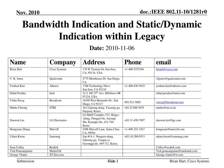
Bandwidth Indication and Static/Dynamic Indication within Legacy. Date: 2010-11-06. Slide 1. Outline. Bandwidth and Static/Dynamic Indications are needed in non-HT PPDUs Inserting a new indication in a non-HT PPDU is complicated

E N D
Bandwidth Indication and Static/Dynamic Indication within Legacy Date: 2010-11-06 Slide 1 Brian Hart, Cisco Systems
Outline • Bandwidth and Static/Dynamic Indications are needed in non-HT PPDUs • Inserting a new indication in a non-HT PPDU is complicated • How to insert Bandwidth and Static/Dynamic Indications into the First 7 Bits in Scrambling Sequence • How to indicate that the First 7 Bits in Scrambling Sequence are modified • Pre-Motion
Bandwidth and Static/Dynamic Indications are Needed in non-HT PPDUs • E.g. Send RTS/CTS duplicated across 80 MHz • Sending RTS/CTS in a non-HT PPDU ensures that all nearby STAs can set their NAV • Using an RTS rather than a new control frame preserves the NAV cancellation feature unique to RTS • RTS + no CTS + no Data => clear NAV • In 11n, the duplication of a frame (e.g. RTS) is not explicitly signaled • Receivers should perform extra, error-prone processing • This gets still more unreliable and expensive with 20/40/80/160/80+80 MHz operation • Static/Dynamic indication in an RTS is needed since it affects CTS behavior. • See 10/1289 RTS/CTS Operation for Wider Bandwidth for a description of Static/Dynamic
Inserting a New Indication in a non-HT PPDU is Complicated • Three bits (2 bits of Bandwidth Indication and 1 bit of Static/Dynamic Indication) need to be inserted • Plus an indication that these bits have actually been inserted (i.e. this is not a pre-VHT non-HT PPDU) • The selected method should have the broadest compatibility with the range of devices already deployed at 5 GHz • Deployed receivers may require that Reserved fields have particular values, else a frame is discarded • Diminishes the purpose of sending an RTS/CTS • A range of options was considered and rejected. For instance: • There is little opportunity to change bits within a) the RTS/CTS MPDU, b) the one Reserved bit in the L-SIG field or c) the nine Reserved bits of the Service field without a reduction in legacy-compatibility • Some important control frames have only 2 Pad bits, and these Pad bits would lack a Tail
Properties of the OFDM Scrambler L-STF, L-LTF, L-SIG DATA SERVICE PSDU, Tail, Pad • Crucially, the mapping between Scrambler Seed and First 7 Bits in Scrambling Sequence is one-to-one • So, defining the First 7 Bits in Scrambling Sequence is equivalent to defining the Scrambler Seed • In the following, we define the scrambler via the First 7 Bits in Scrambling Sequence, instead of via the Scrambler Seed Scrambler Init (0000000) 9 Reserved Zeros XOR Scrambler Seed = 7 random bits (1-127) Scrambling Sequence First 7 Bits in Scrambling Seq = Scrambled DATA First 7 Bits in Scrambling Seq
How to Insert Bandwidth & S/D Indications into First 7 Bits in Scrambling Sequence (1/2) • scramblingSequenceStart4 is randomly chosen from 1-15 • scramblingSequenceStart5 is randomly chosen from 1-31 • Ensures First 7 Bits in Scrambling Sequence is non-zero (and so the Scrambler Seed is non-zero) • Provides reduced yet still good protection against sequences with pathologically poor PAPRs • IsDynamic: 0 (Static), 1 (Dynamic) • Bandwidth: 0 (20 MHz), 1 (40 MHz), 2 (80 MHz), 3 (160 or 80+80 MHz) • Very high compatibility since this First 7 Bits in Scrambling Sequence can arise from a valid Scrambler Seed
How to Insert Bandwidth and S/D Indications into First 7 Bits in Scrambling Sequence (2/2) • Since the first 7 bits of Data In are all-zeros, therefore the shift register input is the same as Scrambled Data Out, and therefore the state of the shift register after 7 bits equals the first 7 Scrambled Data Out bits • Thus the Scrambler Sequence for the remainder of the DATA field is generated by setting the Scrambler State to First 7 Scrambled Bits after 7 bits, and then continuing to run the scrambler as shown above
How To Indicate that the First 7 Bits in Scrambling Sequence are modified by VHT RTS(TA with M/U=M, RA=Responder) VHT Initiator VHT Responder CTS (no TA) • A MAC Address comprises 48 bits with a Unicast/Multicast bit and 47 other bits • The Unicast/Multicast bit in the TA has heretofore been set to Unicast • To indicate that the First 7 Scrambled Bits are modified by VHT, a VHT Initiator sets the Unicast/Multicast bit to Multicast in the TA of a TBD non-response (e.g. RTS) frame carried in a non-HT PPDU sent to a VHT recipient • The VHT Responder doesn’t signal anything explicitly in the response (e.g. CTS) frame – the signaling behavior is inherited from the frame that solicited the response frame • When a VHT Recipient receives a TBD (e.g. RTS) frame with the Unicast/Multicast bit of the TA set to Multicast, the recipient needs to copy the TA and change the Unicast/Multicast bit to Unicast before inserting it as the RA of the response (e.g. CTS) frame • This should have high legacy compatibility • Unchanged response (e.g. CTS) frame • Slightly modified TA in the soliciting frame (e.g. RTS frame), but the RA never matches a pre-VHT STA’s MAC address • No known devices that use the Multicast/Unicast bit of a TA at 5 GHz Third Party
Pre-Motion • Do you support adding to the Specification Frame Work document, the insertion of the Bandwidth and Static/Dynamic indications into the First 7 Bits in Scrambling Sequence as per Slides 6 and 7, with the insertion signaled by the Multicast/Unicast bit of the TA as per Slide 8 • Y/N/A