Download
1 / 26
260 likes | 277 Views
This overview introduces the concept of finite state machines, using an ant in a maze as an example. It discusses the design of an ant brain circuit and the synthesis of next state and output functions. The state minimization process is also explored.

E N D
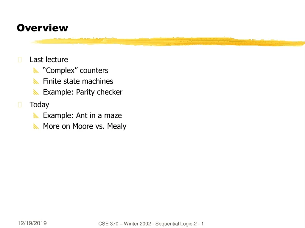
Overview • Last lecture • “Complex” counters • Finite state machines • Example: Parity checker • Today • Example: Ant in a maze • More on Moore vs. Mealy CSE 370 – Winter 2002 - Sequential Logic-2 - 1
Example: ant brain (Ward, MIT) • Sensors: L and R antennae, 1 if in touching wall • Actuators: F - forward step, TL/TR - turn left/right slightly • Goal: find way out of maze • Strategy: keep the wall on the right CSE 370 – Winter 2002 - Sequential Logic-2 - 2
Ant behavior B: Following wall, not touching Go forward, turning right slightly A: Following wall, touching Go forward, turning left slightly D: Hit wall again Back to state A C: Break in wall Go forward, turning right slightly E: Wall in front Turn left until... F: ...we are here, same as state B G: Turn left until... LOST: Forward until we touch something CSE 370 – Winter 2002 - Sequential Logic-2 - 3
L + R L’ R LOST (F) E/G(TL) A (TL, F) L + R L R L’ R’ L’ R’ R L’ R’ B (TR, F) C(TR, F) R’ R’ Designing an ant brain • State diagram CSE 370 – Winter 2002 - Sequential Logic-2 - 4
Synthesizing the ant brain circuit • Encode states using a set of state variables • arbitrary choice - may affect cost, speed • Use transition truth table • define next state function for each state variable • define output function for each output • Implement next state and output functions using combinational logic • 2-level logic (ROM/PLA/PAL) • multi-level logic • next state and output functions can be optimized together CSE 370 – Winter 2002 - Sequential Logic-2 - 5
L + R L’ R state L R next state outputs LOST 0 0 LOST F LOST – 1 E/G F LOST 1 – E/G F A 0 0 B TL, F A 0 1 A TL, F A 1 – E/G TL, F B – 0 C TR, F B – 1 A TR, F ... ... ... ... ... LOST (F) E/G(TL) A (TL, F) L + R L R L’ R’ L’ R’ R L’ R’ B (TR, F) C(TR, F) R’ R’ Transition truth table • Using symbolic statesand outputs CSE 370 – Winter 2002 - Sequential Logic-2 - 6
Synthesis • 5 states : at least 3 state variables required (X, Y, Z) • state assignment (in this case, arbitrarily chosen) LOST - 000 E/G - 001 A - 010 B - 011 C - 100 state L R next state outputs X,Y,Z X', Y', Z' F TR TL 0 0 0 0 0 0 0 0 1 0 0 0 0 0 0 1 0 0 1 1 0 0 ... ... ... ... ... 0 1 0 0 0 0 1 1 1 0 1 0 1 0 0 1 0 1 0 1 0 1 0 1 0 1 0 0 0 1 1 0 1 0 1 0 1 1 0 0 1 1 0 1 0 1 1 0 0 1 0 0 1 1 0 0 1 1 0 1 0 1 0 1 1 0 ... ... ... ... ... it now remainsto synthesizethese 6 functions CSE 370 – Winter 2002 - Sequential Logic-2 - 7
Synthesis of next state and output functions state inputs next state outputs X,Y,Z L R X+,Y+,Z+ F TR TL 0 0 0 0 0 0 0 0 1 0 0 0 0 0 - 1 0 0 1 1 0 0 0 0 0 1 - 0 0 1 1 0 0 0 0 1 0 0 0 1 1 0 0 1 0 0 1 - 1 0 1 0 0 0 1 0 0 1 1 - 0 1 0 0 0 1 0 1 0 0 0 0 1 1 1 0 1 0 1 0 0 1 0 1 0 1 0 1 0 1 0 1 - 0 0 1 1 0 1 0 1 1 - 0 1 0 0 1 1 0 0 1 1 - 1 0 1 0 1 1 0 1 0 0 - 0 1 0 0 1 1 0 1 0 0 - 1 0 1 0 1 1 0 e.g. TR = X + Y Z X+ = X R’ + Y Z R’ = R’ TR CSE 370 – Winter 2002 - Sequential Logic-2 - 8
F TR TL outputlogic next statelogic Next State L R X+ Y+ Z+ Current State X Y Z Circuit implementation • Outputs are a function of the current state only - Moore machine CSE 370 – Winter 2002 - Sequential Logic-2 - 9
L’ R’ L + R L’ R 000 (F) 001(TL) 010 (TL, F) L + R L 101 R L’ R’ R L’ R’ 011 (TR, F) 100(TR, F) 110 R’ 111 R’ Don’t cares in FSM synthesis • What happens to the "unused" states (101, 110, 111)? • They were exploited as don't cares to minimize the logic • if the states can't happen, then we don't care what the functions do • if states do happen, we may be in trouble Ant is in deep trouble if it gets in this state CSE 370 – Winter 2002 - Sequential Logic-2 - 10
State minimization • Fewer states may mean fewer state variables • High-level synthesis may generate many redundant states • Two states are equivalent if they are impossible to distinguish from the outputs of the FSM, i. e., for any input sequence the outputs are the same • Two conditions for two states to be equivalent: • 1) output must be the same in both states • 2) must transition to equivalent states for all input combinations CSE 370 – Winter 2002 - Sequential Logic-2 - 11
L + R L’ R LOST (F) E/G(TL) A (TL, F) L + R L R L’ R’ L’ R’ R L’ R’ B (TR, F) C(TR, F) R’ R’ Ant brain revisited • Any equivalent states? CSE 370 – Winter 2002 - Sequential Logic-2 - 12
L + R L’ R LOST (F) E/G(TL) A (TL, F) L + R L R L’ R’ L’ R’ L’ R’ B/C (TF, F) R’ New improved brain • Merge equivalent B and C states • Behavior is exactly the same as the 5-state brain • We now need only 2 state variables rather than 3 CSE 370 – Winter 2002 - Sequential Logic-2 - 13
state inputs next state outputs X,Y L R X',Y' F TR TL 0 0 0 0 0 0 1 0 0 0 0 - 1 0 1 1 0 0 0 0 1 - 0 1 1 0 0 0 1 0 0 1 1 0 0 1 0 1 - 1 1 0 0 0 1 0 1 1 - 1 0 0 0 1 1 0 0 0 1 1 1 0 1 1 0 0 1 1 0 1 0 1 1 0 1 - 0 1 1 0 1 1 1 - 0 0 0 1 1 0 1 1 - 1 1 0 1 1 0 X X X X X TR Y+ TL X+ F 0 1 0 1 0 1 0 1 0 1 0 1 0 1 0 1 0 1 0 1 0 1 1 1 0 1 1 0 0 1 0 0 0 0 1 0 0 0 1 0 0 0 1 0 0 0 1 0 0 1 0 1 1 0 0 0 1 0 0 1 1 0 0 1 1 0 1 1 1 0 1 1 1 0 1 1 1 0 1 1 R R R R R L L L L L Y Y Y Y Y New brain implementation CSE 370 – Winter 2002 - Sequential Logic-2 - 14
L’ R / TL, F A L / TL L’ R’ / TR, F Mealy vs. Moore machines • Moore: outputs depend on current state only • Mealy: outputs may depend on current state and current inputs • Our ant brain is a Moore machine • output does not react immediately to input change • We could have specified a Mealy FSM • outputs have immediate reaction to inputs • as inputs change, so does next state, doesn’t commit until clocking event react right away to leaving the wall CSE 370 – Winter 2002 - Sequential Logic-2 - 15
0 1 D/1 B/0 0 0 reset 1 0 A/0 1 1 E/1 C/0 0 1 Specifying outputs for a Moore machine • Output is a function of state only • Specify output in the state-diagram state bubble • Example: Detector for 01 or 10 current next reset input state state output 1 – – A 0 0 0 A B 0 0 1 A C 0 0 0 B B 0 0 1 B D 1 0 0 C E 1 0 1 C C 0 0 0 D E 1 0 1 D C 0 0 0 E B 0 0 1 E D 1 CSE 370 – Winter 2002 - Sequential Logic-2 - 16
0/0 B 0/0 reset/0 0/1 1/1 A 1/0 C 1/0 Specifying outputs for a Mealy machine • Output is a function of state and of inputs • Specify outputs on transition arcs • Example: Detector for 01 or 10 current next reset input state state output 1 – – A 0 0 0 A B 0 0 1 A C 0 0 0 B B 0 0 1 B C 1 0 0 C B 1 0 1 C C 0 CSE 370 – Winter 2002 - Sequential Logic-2 - 17
Comparing Moore and Mealy machines • Mealy machines usually have less states • React faster to inputs – don't need to wait for clock • Asynchronous outputs and asynchronous feedback are dangerous • Moore machines are safer to use • Outputs change at clock edge (always one cycle later) • May need more logic to decode state into outputs CSE 370 – Winter 2002 - Sequential Logic-2 - 18
FSM design procedure • FSM-design procedure 1. State diagram and state-transition table 2. State minimization 3. State assignment (or state encoding) 4. Next-state logic minimization 5. Implement the design CSE 370 – Winter 2002 - Sequential Logic-2 - 19
Example: vending machine • Release item after 15 cents are deposited • Single coin slot for dimes, nickels • No change Reset N VendingMachineFSM Open CoinSensor ReleaseMechanism D Clock CSE 370 – Winter 2002 - Sequential Logic-2 - 20
Reset S0 N D S1 S2 N D N D S3 S4 [open] S5 [open] S6 [open] N S7 [open] Example: vending machine (cont’d) • Suitable abstract representation • tabulate typical input sequences: • 3 nickels • nickel, dime • dime, nickel • two dimes • draw state diagram: • inputs: N, D, reset • output: open chute • assumptions: • assume N and D assertedfor one cycle • each state has a self loopfor N = D = 0 (no coin) CSE 370 – Winter 2002 - Sequential Logic-2 - 21
present inputs next outputstate D N state open 0¢ 0 0 0¢ 0 0 1 5¢ 0 1 0 10¢ 0 1 1 – – 5¢ 0 0 5¢ 0 0 1 10¢ 0 1 0 15¢ 0 1 1 – –10¢ 0 0 10¢ 0 0 1 15¢ 0 1 0 15¢ 0 1 1 – –15¢ – – 15¢ 1 Reset 0¢ N 5¢ D N 10¢ D N + D 15¢ [open] symbolic state table Example: vending machine (cont’d) • Minimize number of states - reuse states whenever possible CSE 370 – Winter 2002 - Sequential Logic-2 - 22
Example: vending machine (cont’d) • Uniquely encode states present state inputs next state output Q1 Q0 D N D1 D0 open 0 0 0 0 0 0 0 0 1 0 1 0 1 0 1 0 0 1 1 – – – 0 1 0 0 0 1 0 0 1 1 0 0 1 0 1 1 0 1 1 – – – 1 0 0 0 1 0 0 0 1 1 1 0 1 0 1 1 0 1 1 – – – 1 1 – – 1 1 1 CSE 370 – Winter 2002 - Sequential Logic-2 - 23
Q1 Q1 Q1 Open D1 D0 0 1 1 0 1 0 1 1 X X X X 0 1 1 1 0 0 1 0 0 0 1 0 X X X X 0 0 1 0 0 0 1 1 0 1 1 1 X X X X 1 1 1 1 N N N D D D Q0 Q0 Q0 Example: vending machine (cont’d) • Mapping to logic D1 = Q1 + D + Q0 N D0 = Q0’ N + Q0 N’ + Q1 N + Q1 D OPEN = Q1 Q0 CSE 370 – Winter 2002 - Sequential Logic-2 - 24
N’ D’ + Reset (N’ D’ + Reset)/0 Reset Reset/0 0¢ [0] 0¢ N’ D’ N’ D’/0 N N/0 5¢ [0] 5¢ D D/0 N’ D’ N’ D’/0 N N/0 10¢ [0] 10¢ N’ D’ N’ D’/0 D D/1 N+D N+D/1 15¢ [1] 15¢ Reset’ Reset’/1 Equivalent Mealy and Moore state diagrams • Mealy machine • outputs associated with transitions • Moore machine • outputs associated with state CSE 370 – Winter 2002 - Sequential Logic-2 - 25
Example: vending machine (cont’d) • One-hot encoding (selecting state through a bit-vector process) present state inputs next state outputQ3 Q2 Q1 Q0 D N D3 D2 D1 D0 open 0 0 0 1 0 0 0 0 0 1 0 0 1 0 0 1 0 0 1 0 0 1 0 0 0 1 1 - - - - - 0 0 1 0 0 0 0 0 1 0 0 0 1 0 1 0 0 0 1 0 1 0 0 0 0 1 1 - - - - - 0 1 0 0 0 0 0 1 0 0 0 0 1 1 0 0 0 0 1 0 1 0 0 0 0 1 1 - - - - - 1 0 0 0 - - 1 0 0 0 1 D0 = Q0 D’ N’ D1 = Q0 N + Q1 D’ N’ D2 = Q0 D + Q1 N + Q2 D’ N’ D3 = Q1 D + Q2 D + Q2 N + Q3 OPEN = Q3 CSE 370 – Winter 2002 - Sequential Logic-2 - 26