Download
1 / 32
370 likes | 846 Views
Chapter 8 Traffic Channel Allocation . 曾志成 國立宜蘭大學 電機工程學系 tsengcc@niu.edu.tw. Introduction. What is channel allocation? It covers how a BS should assign traffic channels to the MSs.

E N D
Chapter 8Traffic Channel Allocation 曾志成 國立宜蘭大學 電機工程學系 tsengcc@niu.edu.tw EE of NIU
Introduction • What is channel allocation? • It covers how a BS should assign traffic channels to the MSs. • A given radio spectrum is to be divided into a set of disjointed channels that can be used simultaneously while minimizing interference in adjacent channel by allocating channels appropriately (especially for traffic channels) • Stotalchannels equally partitioned among N cells with each cell with S channels as S=Stotal/N, e.g., 140/7=20 • Channel allocation schemes can be divided in general into Static versus Dynamic • Fixed Channel Allocation (FCA) • Dynamic Channel Allocation (DCA) • Hybrid Channel Allocation (HCA) EE of NIU
A7 A2 A3 A4 A5 A6 A1 Fixed Channel Allocation (FCA) • In FCA, a set of channels is permanently allocated to each cell. • Number of available channels S is divided into sets, the minimum number of channel sets N required is related to the frequency reuse distance D as N = D2/3R2 • If a cell of cluster A1 borrows channel, there should not be interference with cells A2, A3, A4, A5, A6, and A7 • A1,1 : Channels 1-20, A1,2 : Channels 21-40 • A1,3 : Channels 41-60, A1,4: Channels 61-80 • A1,5 : Channels 81-100, A1,6 : Channels 101-120 • A1,7 : Channels 120-140 A1,4 A1,5 A1,3 A1,2 A1,6 A1,7 EE of NIU
Simple Borrowing Schemes • In SB schemes, cell (acceptor cell) that has used all its nominal channels can borrow free channels from its neighboring cell (donor cell) to accommodate new calls. • Borrowingfrom the richest: Borrowing can be done from an adjacent cell which has largest number of free channels. • Borrow-first-available scheme: Select the first free channel found for borrowing using a search algorithm. • To be available for borrowing, the channel must not interfere with existing calls. EE of NIU
A5 A2 A3 A7 A1 A4 A6 c a b c a b c a b c a x b c a b c a b c a b Complex Channel Borrowing using Sectored Cell-based Wireless System • Although x borrows channels from a would violate the reuse distance, the direction of sector x are different from the sector a’s in A2, A3, and, A4 EE of NIU
Simple Channel Borrowing Schemes EE of NIU
Dynamic Channel Allocation (DCA) • In DCA schemes, all channels are kept in a central pool and are assigned dynamically to new calls. • After each call is completed, the channel is returned to the central pool. • Select the most appropriate channel for any call based on current allocation and current traffic, with the aim of minimizing the interference. EE of NIU
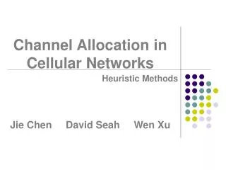
Classification of DCA Schemes • DCA schemes can be centralized or distributed • The centralized DCA scheme involves a single controller selecting a channel for each cell • Centralized DCA schemes can theoretically provide the best performance. • Provide a useful benchmark to compare practical decentralized DCA schemes • The enormous amount of computation and communication among BSs leads to excessive system latencies and renders centralized DCA schemes impractical. • The distributed DCA scheme involves a number of controllers scattered across the network (MSCs) EE of NIU
Centralized DCA Schemes (1/2) • First Available (FA) • The first available channel within the reuse distance encountered during a channel search is assigned to the call. • Locally Optimized Dynamic Assignment (LODA) • Based on the future blocking probability in the neighborhood of the cell where a call is initiated. • Selection with Maximum Usage on the Reuse Ring (RING) • A channel is selected which is in use in the most cells in the co-channel set. • If none is available, the selection is made based on the FA scheme. EE of NIU
Centralized DCA Schemes (2/2) • Mean Square (MSQ) • The MSQ scheme selects the available channel that minimizes the mean square of the distance among the cells using the same channel. EE of NIU
Distributed DCA Schemes • Assigns traffic channels based on one of the three parameters: • Co-channel distance • select channels that neighboring co-channel cells are not using • sometimes adjacent channel interference also taken into account • Signal strength measurement • select channel that the anticipated Co-Channel Interference Ratio (CCIR) is above a threshold • Signal to noise ratio (SNR) • satisfy desired SNR ratio EE of NIU
Comparison between FCA and DCA (1/2) EE of NIU
Comparison between FCA and DCA (2/2) EE of NIU
Other Channel Allocation Schemes • Based on different criterion being used as a potential way of optimizing the performance. • Many other channel allocation schemes have been suggested • Hybrid Channel Allocation (HCA) • Flexible Channel Allocation • Handoff Channel Allocation EE of NIU
Hybrid Channel Allocation (HCA) (1/2) • HCA schemes are the combination of both FCA and DCA techniques. • The total number of channels available for service is divided into fixed and dynamic sets • The fixed set contains a number of nominal channels that are assigned to cells as in the FCA schemes and, in all cases, are to be preferred for use in their respective cells. • The dynamic set is shared by all users in the system to increase flexibility. EE of NIU
Hybrid Channel Allocation (HCA) (2/2) • Request for a channel from the dynamic set is initiated only when the cell has exhausted using all its channels from the fixed set. • Optimal ratio: ratio of number of fixed and dynamic channels • 3:1 (fixed to dynamic), provides better service than fixed scheme when traffic load less than 50% (105 versus 35 channels). • Beyond 50%, fixed scheme perform better. EE of NIU
Channel Allocation in One-Dimensional Systems Call initiated 1 2 3 4 5 6 7 8 a b c d e Reuse distance D If a new call is initiated in cell 1, with the current allocation of channels a, b, c, d, e as shown. It is better to assign channel e to mobile in cell 1. Assuming that as MS in cell 1 moves to cell 2, MS in cell 7 moves to cell 8. EE of NIU
4 3 2 1 Reuse Partitioning-Based Channel Allocation • Each cell is divided into concentric and equal-size zones. • Inner zone being closer to BS would require lesser power to attain a desired channel • MS with the best SIR are assigned a group of channels that have the smallest reuse distance. EE of NIU
Overlapped Cells-Based Channel Allocation Cell 7 • Splitting cell into smaller cells (pico, micro cells), to handle increased traffic. • Highly moving MSs are assigned channels from the cell • MS with low mobility are assigned to micro- or pico-cells 2 6 1 5 3 4 Microcell EE of NIU
C A B Use of Overlapped Cell Areas • If MS in shaded area does not find a free channel in cell A, it can take the free channel from cells B or C. • If a new call in cell A can not find a free channel, some of the existing connections in the shaded area of cell A will be forced to handoff to cells B or C. EE of NIU
System Modeling • The following assumptions are made to obtain an approximate model of system • All MSs are assumed to be uniformly distributed through the cell. • Each MS moves at a random speed and to an arbitrary random direction. • The arrival rate of originating call is given by O. • The arrival rate of handoff call is given by H. • The call service rate is given by . EE of NIU
A Generic System Model for A Cell with S Channels S . . 2 1 H O : service rate O: originating call rate H: handoff call rate Channels EE of NIU
Analysis Model • The following parameters are defined in the analysis model • P(i): the probability of “i” channels to be busy • O: the arrival rate of an originating call in the cell • H: the arrival rate of a handoff call from neighboring cells • BO: the blocking probability of originating calls • S: the total number of channels allocated to a cell • : the call service rate • c: the average call duration EE of NIU
O+ H O+ H O+ H O+ H i-1 0 i S · · · · · · i (i+1) S Basic Modeling (1/3) • The states of a cell can be represented by (S+1) states Markov model. A transition diagram of M/M/S/S model as shown below. State transition diagram EE of NIU
Basic Modeling (2/3) • The state equilibrium equation for state i can be given as • The sum of all states must to be equal to one: • The steady-state probability P(i) is easily found as follows: EE of NIU
Basic Modeling (3/3) • The blocking probability for an originating call when all S channels are busy, can be expressed by: • The blocking probability of a handoff request at this state is also the forced termination probability of a handoff call is BH=BO • This is Erlang B formula covered in Chapter 5 EE of NIU
Modeling for Channel Reservation • Why should we provide a higher priority to handoff calls? • From users’ view, the dropping of handoff calls is more serious and irritating than the blocking of originating calls • How to provide a higher priority to handoff calls? • One approach is reserve SR channels exclusively for handoff calls among the S channels in a cell EE of NIU
System Model with Reserved Channels • System model with reserved channels for handoff • No blocking of originating calls till less than SC channels are busy S . SC . . 2 1 Reserved only for handoff calls H SR O Channels EE of NIU
O+ H O+ H H H · · · · · · SC S 0 SC (SC+1) S Analytical Model (1/3) • The state balance equations can be obtained as and State transition diagram EE of NIU
Analytical Model (2/3) • The steady-state probability P(i) can be obtained as where EE of NIU
Analytical Model (3/3) • The blocking probability BOfor an originating call is given by (at least SC channels busy): • The blocking probability BHfor a handoff call is (all S channels busy) or forced termination probability of handoff call is: EE of NIU
Homework • P8.1 • P8.2 • P8.18 • P8.20 EE of NIU