Download
1 / 46
500 likes | 850 Views
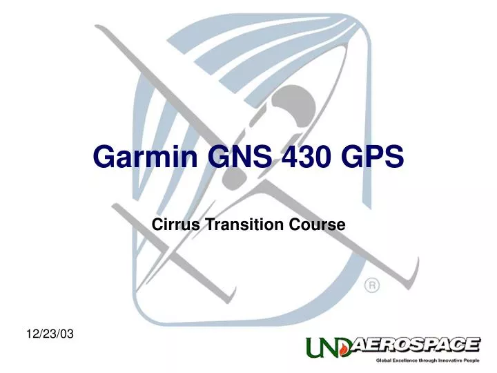
Garmin GNS 430 GPS. Cirrus Transition Course. 12/23/03. The system information, procedures and guidelines found in this presentation are for Reference Only.

E N D
Garmin GNS 430 GPS Cirrus Transition Course 12/23/03
The system information, procedures and guidelines found in this presentation are for Reference Only. The information & procedures in this presentation have been taken from the FAA Approved Airplane Flight Manual and Pilot’s Operating Handbook (POH). The Information & Procedures in this presentation DO NOT SUPERSEDE the Information & Procedures in the POH. In the event of conflict, the POH shall take precedence.
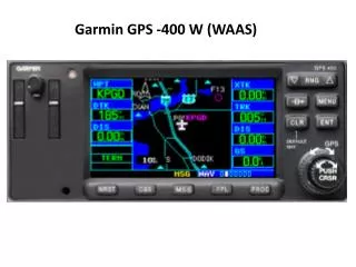
General • Acts as a communications and navigation management system • Integrates radio transceiver, navigation receiver, and GPS navigation capability into a single unit
Functions • C Knob • Power / Com Volume • Squelch • V Knob • VLOC Volume • Ident • C Flip • Moves standby Com frequency to active • V Flip • Moves standby VLOC frequency to active
Functions • Push C/V • Selects between Comm and VLOC frequency selection • Large Knob • Small Knob • Data card 1 • Contains Jeppesen NavData • Data card 2 • Unused
Functions • CDI • Selects between GPS and VLOC navigation data • OBS • Selection inhibits auto sequencing of waypoints • MSG • Displays Message Page • FPL • Displays Flight Plan Chapter • PROC • Displays Instrument Procedures for active waypoint
Functions • RNG • Adjusts moving map • D • Direct To function • MENU • Displays menu for current activity • CLR • Clears data field • Default Nav – Hold for 3 seconds
Functions • ENT • Activates function • PUSH CRSR • Activates cursor for active function • Large Knob • Sequences between data fields • Small Knob • Selects character in current data field
Initialization • Power Up
Initialization • Land Data Initialization
Initialization • Database Cycle • Database Expiration Date
Initialization • Instrument Panel Self-Test
Structure • Chapters • Current chapter identified by white letters at bottom of screen • Pages • Current page number indicated by position of white block at bottom of screen Chapter Page Number
Structure (Nav Chapter) • Nav 1 • Electronic CDI Needle • Active Waypoint • User definable data • Default Nav Page
Structure (Nav Chapter) • Nav 2 • Moving Map • User definable fields at right • Map has three declutter levels, cycled by pressing CLR
Structure (Nav Chapter) • Nav 3 • Frequency information page for active flight plan • Cycles between departure and arrival airports frequency information automatically
Structure (Nav Chapter) • Nav 4 • Position • Commonly used during partial panel operations
Structure (Nav Chapter) • Nav 5 • Satellite Status • Solid bars indicate satellite acquired • Height of bar indicates satellite signal strength • White number below bar indicates satellite number
Structure (Nav Chapter) • Nav 6 • Vertical Navigation (VNAV) • Cannot be used for approach vertical guidance CAUTION
Structure (WPT Chapter) • Wpt 1 • Airport Location • Changes made in WPT chapter do not effect active flight plan or navigation without specific pilot direction
Structure (WPT Chapter) • Wpt 2 • Airport Runway • Information for all airport runways can be viewed by selecting the runway data block and scrolling
Structure (WPT Chapter) • Wpt 3 • Airport Frequencys
Structure (WPT Chapter) • Wpt 4 • Airport Approach
Structure (WPT Chapter) • Wpt 5 • Airport Arrival
Structure (WPT Chapter) • Wpt 6 • Airport Departure • Obstacle DP’s are not included in database • Vector DP’s are not included in database
Structure (WPT Chapter) • Wpt 7 • Intersection
Structure (WPT Chapter) • Wpt 8 • NDB
Structure (WPT Chapter) • Wpt 9 • VOR
Structure (WPT Chapter) • Wpt 10 • User Waypoint
Structure (AUX Chapter) • Aux 1 • Flight Planning
Structure (AUX Chapter) • Aux 2 • Utility
Structure (AUX Chapter) • Aux 3 • Setup 1
Structure (AUX Chapter) • Aux 4 • Setup 2
Structure (NRST Chapter) • Nrst 1 • Nearest Airports
Structure (NRST Chapter) • Nrst 2 • Nearest Intersections
Structure (NRST Chapter) • Nrst 3 • Nearest NDB
Structure (NRST Chapter) • Nrst 4 • Nearest VOR
Structure (NRST Chapter) • Nrst 5 • Nearest User Waypoints
Structure (NRST Chapter) • Nrst 6 • Nearest Center
Structure (NRST Chapter) • Nrst 7 • Nearest Flight Service Station
Structure (NRST Chapter) • Nrst 8 • Nearest Airspace
Structure (FPL Access Key) • Fpl 1 • Active Flight Plan
Structure (FPL Access Key) • Fpl 2 • Flight Plan Catalog • Can store 19 user defined flight plans
Structure (FPL Access Key) • Proc • Instrument Procedures
Operation • VFR Operations