Download
1 / 10
110 likes | 465 Views
8-Bit Timer/Counter 0. Counter/Timer 0 and 2 (TCNT0, TCNT2) are nearly identical. Differences: -TCNT0 can run off an external 32Khz clock (Tosc) or the internal clock after it has passed through the prescaler. -TCNT2 can run off of an external or the internal clock.

E N D
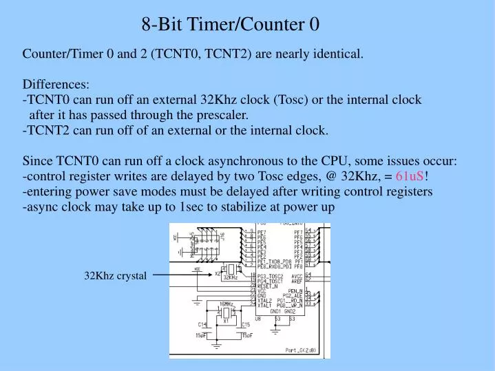
8-Bit Timer/Counter 0 Counter/Timer 0 and 2 (TCNT0, TCNT2) are nearly identical. Differences: -TCNT0 can run off an external 32Khz clock (Tosc) or the internal clock after it has passed through the prescaler. -TCNT2 can run off of an external or the internal clock. Since TCNT0 can run off a clock asynchronous to the CPU, some issues occur: -control register writes are delayed by two Tosc edges, @ 32Khz, = 61uS! -entering power save modes must be delayed after writing control registers -async clock may take up to 1sec to stabilize at power up 32Khz crystal
8-Bit Timer/Counter 0 Counters, timers, PWM generators are all easily implemented. Two interrupt sources exist -overflow (counter register over or under flows) -output compare (counter register = compare register) TCNT0 can be clocked internally or by an external 32Khz clock. The external clock oscillator is optimized for 32.768 Khz watch crystals. Applying a 32.768 Khz oscillator output to the Tosc pins is not recommended.
8-Bit Timer/Counter 0 Four Registers: TCNT0, OCR0, TCCR0, ASSR -TCNT0: (timer/counter register) -the 8-bit counter itself -holds the present value of count -OCR0: (output compare register) -this register is always compared against TCNT0 -TCCR0: (timer/counter 0 control register) -determines the mode of operation -ASSR: (asynchronous status register) -coordinates writing to TCNT0, OCR0, TCCR0 when in asynchronous mode
8-Bit Timer/Counter 0 Timer/Counter 0 Clock Sources: -AS0 bit in ASSR determines if clock source is internal or external -internal clock is fclk @ 16Mhz -external clock is Tosc @ 32Khz Once choice of clock is made, it may be divided by the prescaler by -8, 64, 256, or 1024 If no clock is selected, the timer is stopped and disabled.
8-Bit Timer/Counter 0 Output Compare Unit: -8-bit comparator continuously compares TCNT0 and OCR0. -If equal, the output compare flag is set (OCF0) and an interrupt can be issued. -The waveform generator uses this signal to generate an output to a pin.
8-Bit Timer/Counter 0 Modes of Operation: Determined by -waveform generation mode (WGM01:0) -compare output mode (COM01:0) Normal Mode(WGM1:0 =0) -simplest mode -count up to TOP @ 0xFF and wrap to BOTTOM @ 0x00 -TOV0 flag is set when the wrap around occurs (overflow) -to reset TOV0, ISR must be executed or flag manually cleared -no output pins are enabled
8-Bit Timer/Counter 0 Modes of Operation: Clear Timer on Compare Match (CTC) Mode (WGM1:0 =2) -counter resolution manipulated by output compare register (OCR0) -counter cleared to zero when its value equals OCR0 -TOP defined by OCR0 -interrupt can be generated at compare point -output pin (OC0) can be utilized -output pin can toggle, set, or clear on match -duty cycle constant, frequency is variable OCR0=0xF000 OCR0=0x7F00 OCR0=0x00FF OCR0=0x003F note: fixed duty cycle, variable frequency
8-Bit Timer/Counter 0 Modes of Operation: Fast PWM Mode (WGM1:0 =3) -used to create high resolution PWM waveforms -same frequency, different duty cycle -count from BOTTOM to 0xFF, then reset to BOTTOM -output compare behaviour: -set on compare match -reset at TOP -TOP is defined by OCR0 -limited to 7 different PWM frequencies compare value sets duty cycle value of TOP sets frequency note: fixed frequency, variable duty cyele
8-Bit Timer/Counter 0 Code examples // tcnt0_normal.c // setup TCNT0 in normal mode and blink PB0 LED at 1 sec intervals // blink frequency = (32768)/(2^8 * 64 * 2) = 1.000000 blinks per sec // #include <avr/io.h> int main() { uint8_t count=0; DDRB = 0x01; //set port B bit zero to output ASSR |= (1<<AS0); //use ext oscillator TCCR0 |= (1<<CS00); //normal mode, no prescaling while(1) { while (! (TIFR & (1<<TOV0))){} //spin till overflow TIFR |= (1<<TOV0); //clear by writing a one to TOV0 count++; //extend counter //toggle PB0 every 64 overflows if((count % 64) == 0){PORTB ^= 0x01;} } //while } // main
8-Bit Timer/Counter 0 Code examples // tcnt0_normal_int.c // use interrupts now // setup TCNT0 in normal mode and blink PB0 LED at 1 sec intervals // blink frequency = (32768)/(2^8 * 64) = 1.000000 blinks per sec // #include <avr/io.h> #include <avr/interrupt.h> ISR(TIMER0_OVF_vect){ static uint8_t count=0; //hold value of count between interrupts count++; //extend counter //toggle PB0 each time this happens if((count % 64) == 0){PORTB ^= 0x01;} }//TIMER0_OVF_vect int main() { DDRB = 0x01; //set port B bit zero to output TCCR0 |= (1<<CS00); //normal mode, no prescaling ASSR |= (1<<AS0); //use ext oscillator TIMSK |= (1<<TOIE0); //allow interrupts on overflow sei(); //interrupts turned on while(1) {} //spin forever waiting on interrupts //(note nearly empty main, no need for volatile count variable) } // main