Download
1 / 25
301 likes | 863 Views
SPECIAL IMAGING/ADVANCED IMAGING INTRODUCTION TO DIGITAL RADIOGRAPHY. Tomography- Chapter 21- Bushong CT –Chapter 29 Bushong/Chapter 22-Bontrager MRI – Chapter 24, Bontrager CR/DR- Chapters 1,4, 7-Carter Chapter 12 - Fauber. FACTS ABOUT TOMOGRAPHY.

E N D
SPECIAL IMAGING/ADVANCED IMAGINGINTRODUCTION TO DIGITAL RADIOGRAPHY Tomography- Chapter 21- Bushong CT –Chapter 29 Bushong/Chapter 22-Bontrager MRI – Chapter 24, Bontrager CR/DR- Chapters 1,4, 7-Carter Chapter 12 - Fauber
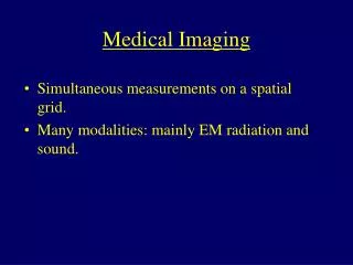
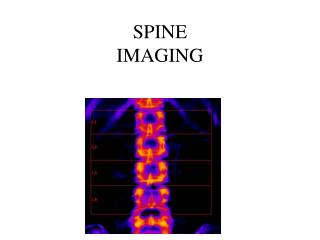
FACTS ABOUT TOMOGRAPHY • Conventional radiography-structures are superimposed • Before widespread use of CT and MRI, tomography was the procedure of choice • TOMOGRAPHY isolates and visualizes a particular section of the body. Blurs out structures above and below the area of interest
DO THE “TOMOMOTION” WITH ME! • X-RAY TUBE IS ATTACHED TO THE IMAGE RECEPTOR (BUCKY). • TUBE MOVES IN ONE DIRECTION, BUCKY IN ANOTHER
FULCRUM (POINT OF PIVOT) • FACTS ABOUT THE FULCRUM • LIES IN OBJECT PLANE • OBJECTS ABOVE AND BELOW THE FULCRUM ARE PROJECTED TO VARIOUS LOCATIONS ON IMAGE RECEPTOR • FULCRUM IS USUALLY ADJUSTABLE • DETERMINES WHAT SECTION OF THE BODY IS NEEDED TO BE VISUALIZED
TOMOGRAPHY ANGLES • Determines the thickness of the “cut” • More Angle = thinner cut
THE ARC • SHOULD BE LONG ENOUGH TO ACCOMMODATE EXPOSURE TIME
WORDS TO AVOID • CUT! • SLICE! • SECTION IS THE BEST DESCRIPTION!
TYPES OF TOMOGRAPHY UNITS • Conventional Movement • Linear • Circular • Elliptical • Hypocycloidal • Trispiral
TYPES OF TOMOGRAPHY UNITS • Zonography • Panoramic Tomography • All tomography exams increase patient dose. A 16 film tomographic exam can equal patient dose of several rad. • Stereoradiography • Magnification Radiography
CT • Conventional tomography produces coronal and sagital images • CT produces transaxial images
CT SIMPLIFIED • Rotating x-ray source • Fan shaped beam • Multiple stationary detectors • Tube rotates around body-translation • Body attenuates x-ray beam • The attenuated beam (pixel) is assigned a CT number (Hounsfield unit) • Computer calculates attenuation of the individual voxels- three dimensional tissue volumes (height, width, depth)-pg 732-Bontrager
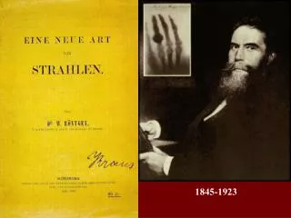
CT HISTORY (KEY WORDS) • Godfrey Hounsfield • EMI scanner • 1st generation • 2nd generation • 3rdgeneration • 4th generation • 5th generation
COMPONENTS OF A CT SCANNERGANTRY • Detectors, track for x-ray tube • Scintillation, gas filled, • High frequency circuit (Low frequency circuit is located in CT room) • X-ray tube (8,000,000+ HU) • Collimation • Two collimators • prepatient • Determines dose profile and patient dose • and predetector • Determines sensitivity profile and slice thickness
HIGH VOLTAGE GENERATOR • ACCOMMODATES HIGHER ROTOR SPEEDS • POWER SURGES OF PULSED SYSTEMS • IN THE GANTRY
Patient support table • Table indexes ( moves at a preset distance when the exam begins) • Movement must be reproducible within 1 mm • In spiral CT table moves continuously • Weight limit of 450 lbs, made with low atomic number
$$$$COMPUTER SYSTEM$$$$ • 1/3 the cost of the entire system • The “brains” of the CT unit • May calculate up to 250,000 mathematical equations simultaneously • Reconstruction time=end of scanning to image appearance
Operating Consoles • Dual Monitors • Operator-turns CT scanner on and off • Selects and can control the protocol which is • Predetermined • Includes kVp, mAs, pitch, FOV,slice thickness, table indexing, reconstruction, algorithms and display windows • KVP and mAs preselected as is focal spot size • kVp usually in excess of 120 kVp • Usual mA station is 100 mA in continuous beam and several hundred mA in pulsed beam • Physicians viewing console
SPATIAL RESOLUTION • DEPENDENT ON: • Focal spot size (not operator controlled: pre determined) • Beam collimation • Detector size • Matrix and pixel size(Larger matrices with smaller pixels= better spatial resolution)
MRI • Magnetize the atomic nuclei in hydrogen atoms • Bombard these atoms with radiofrequency waves • Hydrogen atoms absorb RT and re-emit back as radiowaves. • Signals are sent to computer to construct an image
DIGITAL RADIOGRAPHYCR AND DR REFERENCES: Digital Radiography and PACS, Carter Rad. Imaging and Exposure, Fauber
CASSETTE BASED DR CR: -Imaging plate composed of photostimulable phosphor-Barium fluorohalide crystals doped with europium-Do not fluoresce when hit by x-ray photons, store energy instead.-laser releases the stored energy in a form of light-Collected by photomultiplier tube and converted to digital data. CASSETTE-LESS SYSTEM INDIRECT CAPTURE X-RAYS CONVERTED TO LIGHT LIGHT DETECTED BY AN AREA CCD OR TFT (THIN FILM TRANSISTOR) CONVERTED TO ELECTRICAL SIGNAL DIRECT CAPTURE/CONVERTS X-RAY INTO AN ELECTRICAL SIGNAL DETECTOR REPLACES THE CONVENTIONAL BUCKY CR VS DR
PROCESSING • Film – image produced by interaction of the chemicals with the exposed silver halide crystals • CR- Computer near the reader (digitizer) • DR –computer next to the console
TECHNIQUE • FILM – NON-LINEAR RESPONSE (THINK OF CHARACTERISTIC CURVE) • CR/DR – kVP influences subject contrast but radiographic contrast is controlled by the LUT • CR/DR –mAs affects pt. exposure and image noise but density is controlled by image processing algorithms (with LUT) • CR/DR – more sensitive to scatter
LUT???? • LOOK-UP TABLE • SEE PAGE 115-116 (Carter et al) • REMEMBER EACH PIXEL HAS IT’S OWN GRAY VALUE pg 73 (Carter et al) • Pixel is a picture element • Contains bits of information • Make up the matrix • http://photo.net/equipment/digital/basics/pixels.jpg • To be continued in LAB on March 31/April 4