Download
1 / 21
210 likes | 288 Views
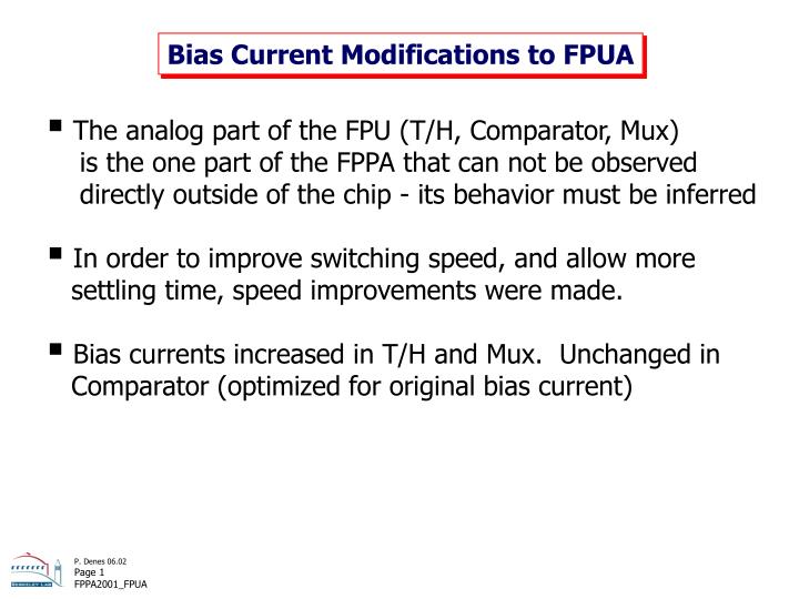
Bias Current Modifications to FPUA. The analog part of the FPU (T/H, Comparator, Mux) is the one part of the FPPA that can not be observed directly outside of the chip - its behavior must be inferred

E N D
Bias Current Modifications to FPUA • The analog part of the FPU (T/H, Comparator, Mux) is the one part of the FPPA that can not be observed directly outside of the chip - its behavior must be inferred • In order to improve switching speed, and allow more settling time, speed improvements were made. • Bias currents increased in T/H and Mux. Unchanged in Comparator (optimized for original bias current)
Sampler TRACK HOLD tAQ tAP LO 0.5V + 1Vbe 2Vbe IN 2Vbe HI 2V - 1Vbe Output tracks input Output held Aperture Delay (tAP) ~100 ps Acquisition Time (tAQ) ~ 2 ns
Multiplexer Select A Select B LO 0.5V + 1Vbe 2Vbe IN 2Vbe HI 2V - 1Vbe IN Break-before-make Slew rate dependent acquisition time
2-Gain FPU (a la FPPA2001) c.f. ModifiedSTRIP.pdf Comparator MX X5 Capbuf Out X5 MUX Out X1 X1 Capbuf Out
Zoom in on Transition MX Break Switch Slew Rate = 600 mV/ns MUX Out
Double Switch Bias Comparator X5 Capbuf Out X5 MUX Out X1 X1 Capbuf Out
Compare 200 A 400 A
Bias Implementation x2 x1 x1 x2
Bias Implementation • Comparator and Capbuf already optimized • at 200 µA and 100 µA • Keep layout unchanged COMPAR. T/H Bias CapBuf MUX
Changed Currents One FPU channel Was Is 1k 500 1k CapBuf Compar MUX T/H 200 200 400 200 400 100 200 250 Bias Generator 200µ 405µ 200µ 240µ 200µ 240µ 350µ 660µ 1k500 Factor 2 Power(FPU)=22 mW
Preamp Gain Comp. S/H MUX 1 5 AD9042 9 Buf 33 In I,V,Refs Ref Logic Follow Through the Chain
Preamp Gain Stage • 60 pC injection shown • BW fixed by xN stages x1 Output Preamp Output Top Level Simulation with All Parasitics
Gain Stages Max. valid preamp output x1 x9 x5 x33 • Clamping Outputs Top Level Simulation with All Parasitics
Gain Stage T/H Top Level Simulation with All Parasitics
T/H Details • Fast TH • Slower HT Top Level Simulation with All Parasitics
Large-Signal Response x1 x9 x5 x33 Mux Out Top Level Simulation with All Parasitics
MUX Commands (from Comparators) x33 x9 x5 x1 Top Level Simulation with All Parasitics
x1 Mux • CKiMX = 9.7 ns (recall internal delay) Top Level Simulation with All Parasitics
x5 Mux • CKiMX = 9.7 ns Top Level Simulation with All Parasitics
x9 Mux • CKiMX = 9.7 ns Top Level Simulation with All Parasitics
x33 Mux • CKiMX = 9.7 ns Top Level Simulation with All Parasitics