Download
1 / 34
340 likes | 453 Views
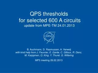
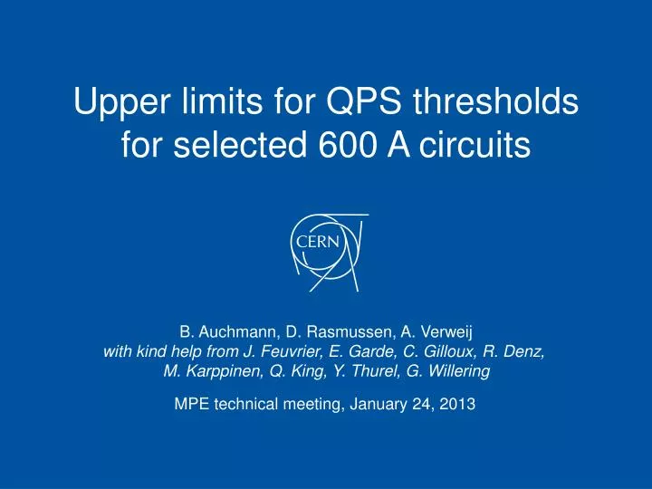
Upper limits for QPS thresholds for selected 600 A circuits. B. Auchmann, D. Rasmussen, A. Verweij with kind help from J. Feuvrier , E. Garde , C. Gilloux , R. Denz , M. Karppinen , Q. King, Y. Thurel , G . Willering. MPE technical meeting, January 24, 2013. Motivation.

E N D
Upper limits for QPS thresholds for selected 600 A circuits B. Auchmann, D. Rasmussen, A. Verweij with kind help from J. Feuvrier, E. Garde, C. Gilloux, R. Denz, M. Karppinen, Q. King, Y. Thurel, G. Willering MPE technical meeting, January 24, 2013
Motivation • Request: compute limits for QPS thresholds of the following circuit types (incl. current thresholds):
validation of the quench model • propagation • coupling losses • circuit model • magnet protection • busbar protection • recommendation
Validation quench propagation 1/2 • All concerned magnets use the same strand/insulation/impregnation – wire#3. • RQTD/F and RQTL circuits are the most critical (assumption later proven by simulation). • Bloc 4 data of initial voltage rise up to 2 V available at 400 A and 600 A from magnet training, as well as current decays. • Top = 4.2 K, Rcrowb = 27 mΩ, Uth = 50 mV, Δtdiscr = 10 ms • ROXIE thermal model: • transversal discretization: 1 temperature node per turn. • ROXIE longitudinal discretization: coarse (6cm) to limit computation time. • QP3 used to compare longitudinal propagation velocity for 1 mm (converged) and 6 cm discretization at different current- and field levels.
Validation quench propagation 2/2 400 A 400 A Zoom 600 A 600 A
Validation quench-back by IFCL • Simulation of FPA at different current levels. • Tune IFCL effective resistivity ρeff and time constant τ to match observed quench-back.
Quenching mechanisms • RQT, Iq = 400 A
Quenching mechanisms • RQT, Iq = 600 A
Validation R(t) • Comparing MQTL data from Bloc 4 to ROXIE simulation
ROXIE circuit model R// R//ext Quenching magnet and its R//, Ld(I), quench resistance External circuit elements; constant Ld, no quenches Ld Rq Ld,ext Rleads Rcrowb REE voltage regulated power supply Vmax= 10 V, Δtperiod=80/100ms EE switch opened by QPS after validation delay and switch delay crowbar triggered via QPS or if ΔI > 10 A QPS triggers on Ures= RqImag
RQTD/F, ROXIE vs. PSpice • Use R(t) from ROXIE in PSpice model to validate new ROXIE circuit model. • Differences due to constant external magnet inductance in ROXIE. R// R//ext Ld Rq Ld,ext Rleads Rcrowb REE
validation of the quench model • magnet protection • busbar protection • recommendation
Worst-case protection scenario • Show that magnets are protected by FGC and parallel resistors alone, i.e., Tmax < 200 K. • Magnet protection is virtually independent from QPS thresholds; we model for Uth = 1 V, Δtdiscr= 200 ms. • Determine maximal permissible QPS thresholds for protection of busbars. • The resulting limits can only improve the protection of the magnets.
RQTD/F, Iq = 600 A • Circuit: 8 magnets, R// = 0.25 Ω, REE = 0.7 Ω, Rcrowb = 0.05 Ω, Rlead = 0.006 Ω • FGC: Δtperiod=80 ms, Vmax = 10 V, ΔImax = 10 A. • QPS: Vth = 1 V, Δtdiscr=200ms
Summary magnet protection • Due to large cu/sc ratio and low position on the loadline (max ~60%), magnets are very robust. • FGC and R// provide ultimate protection, virtually independently from QPS thresholds. • Failure of R// • is VERY unlikely – robust design! • would not be fatal. • R// is dimensioned to absorb the energy of an entire RQTD/F circuit with Tmax = 400 K. • Also studied: • HF/LF quench locations; • different quench timing w.r.t. FGC regulation period; • neither has significant impact.
validation of the quench model • magnet protection • busbarprotection • recommendation
Protection of the 600 A busbar Worst case scenario: Quench starts in a thermally insulated part of the bus. Quench propagates not or slowly outside the insulated part (so good cooling to LHe). Global voltage built-up is small even though local hot-spot can be high. busbar Helium 6 cm long plug Parameters used: Cross section bus: 2 mm2 with Cu/Sc ratio=9 Bus insulation: 0.2 mm kapton Cooling: 600-1200 W/K/m2 Lcircuit=0.248 H Rcircuit=0.23-0.7 W
Worst case scenario combined with: • high QPS threshold: 0.8 and 1 V, • long QPS discr time: tdiscr=190 ms, • Rcircuit=0.23 W. Conclusion: 0.8 V, 190 ms is safeup to 600 A, for all busbars with tEE<1.1 s.
validation of the quench model • magnet protection • busbarprotection • recommendation
Recommendation • The busbar protection defines the upper limit for QPS thresholds of all studied circuits:Uth ≤ 0.8 V, Δtdiscr≤ 190 ms • Respecting these limits, set thresholds to the lowest practicable values.
Caveat? RPMBB-type has no DC cont.
Validation MIITs vs. ROXIE • ROXIE temp. slightly below MIITs estimate (propagation). • Calculated MIITs: 0.037 kA2s, Tmax = 235 K, Bpeak = 4 T
RQTD/F, Iq = 600 A, R// failure M. Karppinen: Failure VERY unlikely – robust design! R// is designed to absorb the energy of an entire RQTD/F circuit with Tmax = 400 K.
RQTL • RQTL9: 2 magnets, R// = 0.2 Ω, REE = 0.7 Ω, Rcrowb = 0.05 Ω, Rlead = 0.002 Ω • RQTL7-8/10-13: 1 magnets, R// = 0.2 Ω, no EE, Rcrowb = 0.05 Ω, Rlead = 0.002 Ω • FGC: Δtperiod=100ms, Vmax = 10 V, ΔImax = 10 A. • QPS: Vth = 1 V, Δtdiscr=200ms • In the Δtdiscr=200 ms / POWERING_FAILURE scenario, REE is not instrumental. We study RQTL9 as a worst case.
Effect of 10V PC output voltage during 1 period before POWERING_FAILURE, PSpice
RSS, Iq = 600 A • Circuit: 4 magnets, R// = 0.15 Ω, REE = 0.7 Ω, Rcrowb = 0.05 Ω, Rlead = 0.003 Ω • FGC: Δtperiod=100ms, Vmax = 10 V, ΔImax = 10 A. • QPS: Vth = 1 V, Δtdiscr=200ms
RO, Iq = 600 A • Circuit: 13 magnets, no R//, REE = 0.7 Ω, Rcrowb = 0.05 Ω, Rlead = 0.003 Ω • FGC: Δtperiod=100ms, Vmax = 10 V, ΔImax = 10 A. • QPS: Vth = 1 V, Δtdiscr=200ms
IFCL induced quenches during FPA in RQTD/F • Preliminary study: to avoid quenches up to 600 A, REE would need to be reduced to 0.1 Ω. • Any reduction in REE reduces the number of quenches and the test voltages. • Busbar protection calculation assumed REE = 0.23 Ω.