Download
1 / 14
160 likes | 205 Views
Explore the relationship between mutual inductance and electrical circuits with practical examples and experimental methods. Learn about the efficiency and ideal characteristics of transformers.

E N D
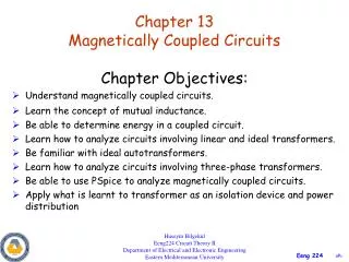
MAGNETIC COUPLED CIRCUITS Celso José Faria de Araújo, Dr.
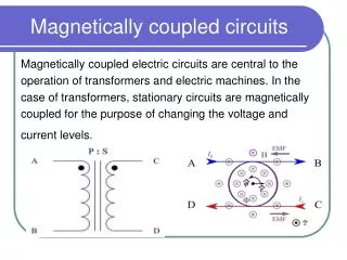
Mutual Inductance Magnetic Coupled Circuits Electrical Circuits - Celso José Faria de Araújo, M.Sc.
Mutual Inductance (Equivalent Circuits) Magnetic Coupled Circuits Electrical Circuits - Celso José Faria de Araújo, M.Sc.
Mutual Inductance (Examples 1 and 2) Magnetic Coupled Circuits Electrical Circuits - Celso José Faria de Araújo, M.Sc.
Mutual Inductance (Examples 3) Magnetic Coupled Circuits Electrical Circuits - Celso José Faria de Araújo, M.Sc.
Mutual Inductance (Example 4) Magnetic Coupled Circuits Electrical Circuits - Celso José Faria de Araújo, M.Sc.
Experimental Determination of Mutual Inductance Method One Method Two Magnetic Coupled Circuits Electrical Circuits - Celso José Faria de Araújo, M.Sc.
The Coefficient of Coupling “k” will be equal to unity (100%) only if all of the magnetic flux produced by the first circuit links the second. Magnetic Coupled Circuits Electrical Circuits - Celso José Faria de Araújo, M.Sc.
The Transformer Efficiency or Yield Magnetic Coupled Circuits Electrical Circuits - Celso José Faria de Araújo, M.Sc.
The Linear Transformer • Doesn’t matter where the points are located the input impedance remain the same. • If the mutual inductance “M” is equal zero (decoupled) the input impedance is only Z11 as expected. • The termis called “Reflected Impedance” seen by the input side. Magnetic Coupled Circuits Electrical Circuits - Celso José Faria de Araújo, M.Sc.
The Ideal Transformer • ZIN is called “Reflected Impedance” seen by the left side. • Is characterized by N1/N2 called the turns ratio. • The Coefficient of Coupling takes on its maximum value k=1. • L1 and L2 are permitted to approach infinity, but in such a way that their ratio remains constant. • The efficiency is 100% seen by the left side seen by the right side Magnetic Coupled Circuits Electrical Circuits - Celso José Faria de Araújo, M.Sc.
The Ideal Transformer (Example) Magnetic Coupled Circuits Electrical Circuits - Celso José Faria de Araújo, M.Sc.
The Matching Transformer Source MatchingTransformer Load • In order to maximize power transfer to the load it’s necessary to have: Magnetic Coupled Circuits Electrical Circuits - Celso José Faria de Araújo, M.Sc.
References • Ruston, Henry. Bordogna, Joseph. – Electric Network: Functions, Filters, Analysis – McGraw-Hill Book Company. • Bessonov ,L. – Applied Electricity for Engineers – Translated from the Russian by Boris Kuznetsov – MIR Publishers – Moscow. • Balabanian, N.; Bickart, T. A. – Electrical Network Theory – John Wiley & Sons, Inc - USA Magnetic Coupled Circuits Electrical Circuits - Celso José Faria de Araújo, M.Sc.