Download
1 / 13
130 likes | 225 Views
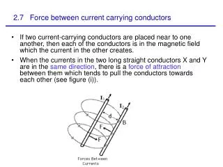
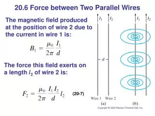
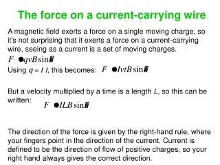
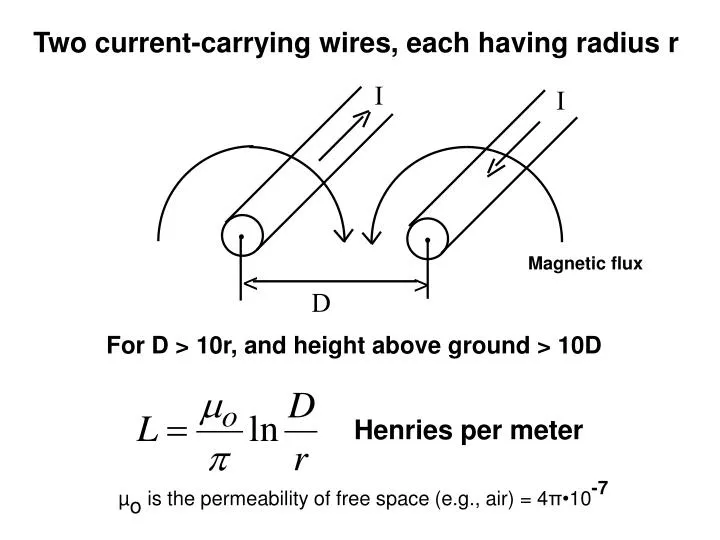
I. I. Magnetic flux. <. >. D. For D > 10r, and height above ground > 10D. Two current-carrying wires, each having radius r. Henries per meter. µ o is the permeability of free space (e.g., air) = 4 π• 10 -7. D. <. >. V. Same two wires, energized by V. Farads per meter.

E N D
I I Magnetic flux < > D For D > 10r, and height above ground > 10D Two current-carrying wires, each having radius r Henries per meter µo is the permeability of free space (e.g., air) = 4π•10-7
D < > V Same two wires, energized by V Farads per meter εo is the permittivity of free space (e.g., air) = 8.854•10-12
< > D Velocity of propagation of disturbances down a lossless overhead transmission line
If Each Conductor is Actually a Bundle Double Bundle, Each Conductor Has Radius r A Equivalent Radius of the Bundled Conductors
250 km Bus 2 DFW 500 km Bus 6 COAL 300 km Bus 7 WIND 400 km Bus 3 UT Bus 1 HOU 150 km 300 km Bus 4 SA No Wind (Good Wind) 400 km • Summer Peak, 3 kW per person, 20 million people, 60 GW • Winter Peak, 80% of Summer Peak • Spring/Fall Peak, 50% of Summer Peak • Nightime, 50% of Daily Peak • Approx 5% losses Bus 5 VAL • Positive-sequence line constants for each 345kV a-b-c circuit: • R = 0.06 Ω/km per conductor • L = 1 µH/m • C = 12 pF/m • Rating = 800 A per conductor • Two conductors per phase • Three phases per circuit • 200kV line-to-ground • Approx. 1 GW per circuit
250 km Bus 2 DFW 500 km Bus 6 COAL 300 km Bus 7 WIND 400 km Bus 3 UT Bus 1 HOU 150 km 300 km Bus 4 SA 400 km Bus 5 VAL No wind in West Texas in summer (HOU makes up WIND gen. in summer) • Positive-sequence line constants for each 345kV a-b-c circuit: • R = 0.06 Ω/km per conductor • L = 1 µH/m • C = 12 pF/m • Rating = 800 A per conductor • Two conductors per phase • Three phases per circuit • Each conductor is 200kV line-to-ground • Approx. 1 GW per circuit • Each 100 km of circuit has • R = 3 Ω • ZL = j37.7 Ω • ZC = -j2210 Ω • 3 GW load corresponds to 40Ω on each a-b-c phase • Summer Peak, 3 kW per person, 20 million people, 60 GW • Winter Peak, 80% of Summer Peak • Spring/Fall Peak, 50% of Summer Peak • Nightime, 50% of Daily Peak • Approx 5% losses
Bus 2 DFW Bus 6 COAL Bus 7 WIND Bus 3 UT Bus 1 HOU Bus 4 SA Bus 5 VAL 6 3 ??? ??? ??? ??? 3
Bus 2 DFW Bus 6 COAL Bus 7 WIND Bus 3 UT Bus 1 HOU 3.0 j37.7 Bus 4 SA -j2210 -j2210 Ohms for 1 phase of a 100km three-phase circuit Bus 5 VAL 40 Ω 40 Ω 40 / 2 Ω 40 / 5 Ω 250km 6 500km 3 300km 2 400km 6 2 40 Ω 150km 300km 6 40 / 6 Ω (on each a-b-c phase) 40 / 4 Ω 3 GW load corresponds to 40Ω on each a-b-c phase 400km 3