Download
1 / 22
220 likes | 326 Views
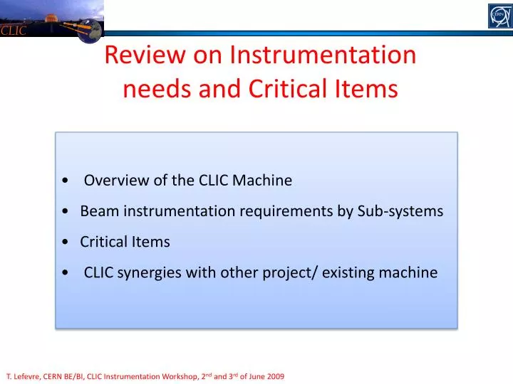
CLIC. Review on Instrumentation needs and Critical Items. Overview of the CLIC Machine Beam instrumentation requirements by Sub-systems Critical Items CLIC synergies with other project/ existing machine. T. Lefevre, CERN BE/BI, CLIC Instrumentation Workshop, 2 nd and 3 rd of June 2009.

E N D
CLIC Review on Instrumentation needs and Critical Items • Overview of the CLIC Machine • Beam instrumentation requirements by Sub-systems • Critical Items • CLIC synergies with other project/ existing machine T. Lefevre, CERN BE/BI, CLIC Instrumentation Workshop, 2nd and 3rd of June 2009
CLIC 3TeV CLIC CR1 CR1 Drive Beam accelerator Combiner rings Drive Beam accelerator Delay Loop Delay Loop CR2 CR2 Turn around Transfer to tunnel Long Transfer lines Product Breakdown Structure Decelerators Post Deceleration lines Post Collision line BC2 BDS IP1 e- main linac e+ main linac Long Transfer lines Turn around Transfer to tunnel Talk on Wednesday afternoon Booster linac BC1 e- PDR e- DR e+ DR e+ PDR Injector Linac Thermoionic gun e- DC polarized gun e- e- / e+ target Pre-injector linac for e- Pre-injector linac for e+ Primary e- linac for e+
Challenges for CLIC Main Beam CLIC CR1 CR1 Drive Beam accelerator Combiner rings Drive Beam accelerator Delay Loop Delay Loop CR2 CR2 • Producing and measuringsmall beam emittance (1micron) • Producing and measuring short Bunches (45microns) • Conserving small beam emittance (very strict tolerances/requirements on the beam position monitor precision and resolution) Turn around Transfer to tunnel Long Transfer lines Decelerators Post Deceleration lines Post Collision line BC2 BDS IP1 e- main linac e+ main linac Long Transfer lines Turn around Transfer to tunnel Final Focus gex : 0.66 mm.mrad gey : 0.02mm.mrad DE/E : 0.35% sx = 40 nm sy = 1 nm Entrance linac gex : 0.60 mm.mrad gey : 0.01 mm.mrad DE/E : 1.5% sz : 45mm (150fs) Booster linac BC1 e- PDR e- DR e+ DR e+ PDR Damping ring gex : 10 -> 0.381 mm.mrad gey : 10 -> 0.004 mm.mrad DE/E : 0.134% sz : 1.5mm (5ps) Injector Linac Thermoionic gun e- DC polarized gun e- e- / e+ target Pre-injector linac for e- Pre-injector linac for e+ Primary e- linac for e+
Challenges for CLIC Drive Beam CLIC CR1 CR1 Drive Beam accelerator Combiner rings Drive Beam accelerator Delay Loop Delay Loop CR2 CR2 Turn around Transfer to tunnel Long Transfer lines Drive Beam frequency multiplication complex sz : 2mm (6.6ps) I : 4.2 – 8.4 - 25.2 - 101A Db : 60 - 30 - 10 - 2.5cm 24 Drive Beam decelerators I : 101A ; Dt=241ns ge : 150 mm.mrad sz : 1mm (3.3ps) 2.38GeV 238MeV Drive Beam accelerator I : 4.2A ; Qb : 8.4nC : Dt : 140ms ge : < 100 mm.mrad DE/E : <1% sz : 4mm (13.3ps) Decelerators Post Deceleration lines Post Collision line BC2 BDS • Manipulating high charge beams (Machine Protection issues, Radiation level, Non intercepting beam diagnostic, ..) • In addition, there are very strict tolerances/requirements on the beam phase stability (0.1º@12GHz) • Reliability and availability : This is ‘just’ the RF Source ! IP1 e- main linac e+ main linac Long Transfer lines Turn around Transfer to tunnel High efficiency high power 12GHz RF source ‘How to transform a long low current low frequency beam into a series of short beams with a high current and a high frequency’ Booster linac Final time structure BC1 Initial time structure e- PDR e- DR e+ DR e+ PDR 140 ms length – 4.2A @ 2.4GeV 60cm between bunches Injector Linac Thermoionic gun e- DC polarized gun e- e- / e+ target 24 x 240ns pulse spaced by 5.8ms 101A, 2.5cm between bunches Pre-injector linac for e- Pre-injector linac for e+ Primary e- linac for e+
CLIC CR1 CR1 CLIC 3TeV Drive Beam accelerator Combiner rings Drive Beam accelerator Delay Loop Delay Loop CR2 CR2 CLIC RF source • 2 Drive beam accelerators (2x 1km) • 2 Delay loop and 4 Combiner rings (2x 657m) • 2 Long Transfer lines (2x 21km) • 48 Turn arounds (48x 107m) • 48 Drive beam decelerators (48x 900m) Turn around Drive Beam ~ 93kms of beam lines Transfer to tunnel Long Transfer lines Decelerators Post Deceleration lines Post Collision line BC2 BDS IP1 e- main linac e+ main linac Long Transfer lines Turn around Transfer to tunnel • Electron/positron injectors (600m) • Damping rings (4x500m) • Bunch compressor 1 (2x 70m) • Booster Linac (600m) • Long transfer lines (2x 21km) • Turn around (2x 1.6km) • Bunch compressor 2 (2x 120m) • Main Linac (2x 20.8km) • Beam Delivery System (2x 2.75km) • Post Collision line (2x 250m) Booster linac Main Beam ~ 96kms of beam lines BC1 e- PDR e- DR e+ DR e+ PDR Injector Linac Thermoionic gun e- DC polarized gun e- e- / e+ target Pre-injector linac for e- Pre-injector linac for e+ Primary e- linac for e+
CLIC CLIC 3TeV • Beam Position (x / y) • Bunch length (sz) • Beam Current I • Beam Phase • Luminosity • Beam Halo or Tail • Beam Polarization • Beam losses • Beam energy E and energy spread DE • Beam size (sx / sy)
CLIC Parameter specifications List of instruments for each sub-systems Identify the critical items in each of the 44 sub-systems (feasibility, cost, performance) Identifyneed for Commissionning / Production Beams
CLIC 3TeV – Numbers of devices CLIC Drive Beam 47011 devices No Beam Loss Monitors specified yet Main Beam 8226 devices + 142812 wakefield monitors
From 500GeV to 3TeV CLIC
CLIC Tunnel CLIC Courtesy of J. Osborne and A. Samoshkin
List of Critical Items CLIC • Very tight requirements for measuring micrometer beam size, 40-75microns short bunch length and beam position with a 50nm resolution • Reliability and availability of roughly 5000 high resolution (50nm) BPMs, 40000 BPM’s for the Drive Beam Decelerator and 150000 wakefield monitors with 5mm accuracy • Need to study theMachine Protection System for both the Drive and Main beams and to develop a Beam loss monitoring system along the CLIC linac (both beams) • Beam synchronization implies a 0.1deg at 12GHz phase measurement with an adequate feed-forward system (a stability of the Drive Beam energy and intensity of 3.10-5): need a non destructive energy measurements between each CLIC Main Beam sectors
Several steps for the CDR CLIC • 1- Collect the beam instrumentation requirements for each CLIC sub-systems and identify Critical Items and the need for new R&D • 2- Evaluate the performance of already-existing technologies • CLIC specific instruments • - Luminosity monitors • - 20-50fs timing synchronization • CTF3 beam diagnostics – importable to CLIC • ILC instruments with similar requirements as for CLIC • Laser Wire Scanner or Cavity BPM • Beam Delivery System instrumentation • Ex: Polarization monitor, Beam Energy measurements • Damping ring instrumentation developed at ATF2 • 3rd and 4th generation light sources • Damping ring instrumentation • Bunch Compressor instrumentation very similar to XFEL projects
CLIC vs CTF3 CLIC The thermal limit for ‘best’ material (C, Be, SiC) is 106 nC/cm2 • Still considerable extrapolation to CLIC parameters • Especially total beam power (loss management, machine protection) • Development of non-destructive instruments • Stability and reliability
CLIC vs ILC CLIC Requirements for CLIC are always tighter Critical Beam Parameter http://clic-study.web.cern.ch/CLIC-Study/ http://www.linearcollider.org/cms/
CLIC vs Light Sources CLIC Development of BLM for long linac
CLIC Instrumentation CLIC CR1 CR1 Drive Beam accelerator Combiner rings Drive Beam accelerator Delay Loop Delay Loop CR2 CR2 Turn around Transfer to tunnel Long Transfer lines Decelerators Post Deceleration lines Post Collision line BC2 BDS IP1 e- main linac e+ main linac Long Transfer lines Turn around Transfer to tunnel Booster linac BC1 Beam diagnostics from e- PDR e- DR e+ DR e+ PDR Light sources ILC CTF3 Injector Linac Thermoionic gun e- DC polarized gun e- e- / e+ target Pre-injector linac for e- Pre-injector linac for e+ Primary e- linac for e+
Perspectives CLIC • Huge amount of work: 200000 Instruments over 190kms of beamlines • R&D on Critical Items has started and the status is presented during the next two sessions • Big potential for collaborations with light sources community • Discussion sessions on Wednesday Afternoon • Define the frame of the work for the CDR • Review Plans & Milestones for every Critical Instruments • Work to be done for a Cost estimate
CLIC Instrumentation and ressources • Development on Beam loss monitors • Recent collaboration with University of Liverpool - Cockcroft Institute for Beam loss detection technique based on Optical fiber • Recent collaboration with Greece : Students for beam loss shower simulations • Development of micrometer beam size monitor • JAI-RHUL and Oxford University colleagues involved in ATF2 laser wire scanner program • - Development of short bunch length monitoring techniques • INFN-Frascati for RF deflector techniques • Northwestern University using RF pick-up techniques • JAI-RHUL for Coherent Diffraction radiation techniques • Recent interest from University of Dundee for Electro-optics techniques • Development of Beam Position Monitors • FNAL collaboration for 50nm resolution BPM • JAI-RHUL for BPM development • IFIC Valencia for Drive Beam Decelerator BPM • CEA/IRFU for re-entrant cavity BPM • INFN-Frascati for Drive Beam delay loop and combiner rings • Development of Wakefield monitors by CEA/IRFU • Development of emittance and energy spread measurement devices with PSI • Development of post collision line monitor (luminosity monitor) by Uppsala university • Beam synchronization implies a 0.1deg at 12GHz phase measurement with an adequate feed-forward system • Activity not follow-up by the BI group (RF group and FP7) • Electronic development for Large distributed systems: • LAPP for the acquisition system (rad-hard analog and digital solutions) • University Politecnica de Catalunya for rad-hard analog electronic
EuCARD WP9 “NCLinac” Full name: “Technology for normal conducting higher energy linear colliders” 5 tasks: NCLinac Coordination and Communication Normal conducting High Gradient Cavities PETS, alignment & HOM’s, breakdown simulation, BD diagnostics, precise assembly Linac and Final Focus Stabilisation Quadrupole mock-up, FF test-stand Beam Delivery System tuning procedures at ATF2, high-precision BPM’s, Laser-wire Drive Beam Phase control 20 fs RF monitor, electro-optical monitor Partners: CERN, CIEMAT, CNRS, INFN, PSI, RHUL, STFC, UNIMAN, UOXF-DL, UU • Resources: 6.5 MEuros, 540 persons-years
Damping Rings diagnostics • Turn by turn transverse profile monitors (X-ray?) with a wide dynamic range: • Hor. geometrical emittance varies from 11nm.rad @ injection to 90pm.rad @ extraction and the vertical from 270pm.rad to 0.9pm.rad. • Capable of measuring tails for IBS • This would probably be the most challenging item • Longitudinal profile monitors • Energy spread of 0.5% to 0.1% and bunch length from 10 to 0.1mm. • Note that the dispersion around the ring is extremely small (<12mm). • Fast beam loss monitoring and bunch-by-bunch current measurements • E-cloud + ion diagnostics • 300PUs, turn by turn (every 1.6μs) • 10μm resolution, forlinear and non-linear optics measurements. • 2μm resolution for orbit measurements (vertical dispersion/coupling correction + orbit feedback). • WB PUs for bunch-by-bunch (bunch spacing of 0.5ns for 312 bunches) and turn by turn position monitoring with high resolution (1μm) for injection trajectory control, and bunch by bunch transverse feed-back. • PUs for extraction orbit control and feed-forward. • Tune monitors and fasttune feed-back with precision of 10-4, critical for resolving instabilities (i.e. synchrotron side-bands, ions)
Intro: ILC Beam Instruments ILC ~ 6000 Devices CLIC ~ 190000 Devices CLIC@500GeV ~32000 Devices Marc Ross ~ 2000 Button/stripline BPM’s (10-30 / 0.5 µm resolution) ~ 1800 Cavity BPM’s (warm, 0.1-0.5 µm resolution) 620 Cavity BPM’s (cold, part of the cryostat, ~ 1 µm) 21 LASER Wirescanners (0.5-5 µm resolution) 20 Wirescanners (traditional) 15 Deflecting Mode Cavities (bunch length) ~ 1600 BLM’s Other beam monitors, e.g. toroids, bunch arrival / beam phase monitors, wall current monitors, faraday cups, OTR & other screen monitors, sync light monitors, streak cameras, feedback systems, etc. Read-out & control electronics for all beam monitors