Download
1 / 65
680 likes | 1.11k Views
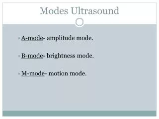
Display Modes. A-Mode or Amplitude Mode B-Mode (Brightness Mode) M-Mode (Motion Mode) . A-Mode. a one-dimensional display or image each pulse produces a new line of information on the display temporal resolution = PRP

E N D
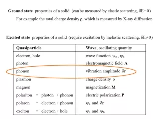
Display Modes • A-Mode or Amplitude Mode • B-Mode (Brightness Mode) • M-Mode (Motion Mode)
A-Mode • a one-dimensional display or image • each pulse produces a new line of information on the display • temporal resolution = PRP • an uncommon display, except in ophthalmologic sonography used for precise intraocular length measurements
A-Mode Height of the spike is proportional to the amplitude
A-Mode Depth… horizontal axis corresponds to the reflector’s depth or distance
B-Mode (Brightness Mode) • - basis for gray scale, two-dimensional (2D) imaging • US unit tracks the position of the transducer to place a dot on the screen corresponding to the transducer position (X, Y locations), creating a 2D image
B-Mode (Brightness Mode) • Each pulse from the transducer creates a single scan line from a series of returning echoes • A complete scan line resulting from one emitted pulse. occurs in < 1/1000 of a second (< 1 msec)
Scan Line One pulse of ultrasound generates a single scan line (from a series of returning echoes). A complete scan line resulting from one emitted pulse. This is accomplished in < 1/1000 of a second. Echoes are presented in sequence on a scan line as they return from tissue. (A) The first echo is displayed. (B) The second echo is added. (C) More echoes are added. (D) All the echoes from a single pulse have been received and displayed as a completed scan line.
B-Mode 0 1 2 3 4 A shade of gray is assigned to the amplitude of the echo Stronger echo amplitude= brighter dots Vertical axis represents depth
M-Mode (Motion Mode) - one-dimension image used to investigate moving structures with respect to time • Temporal resolution = PRP;each pulse produces a new line of echo information on the display • evaluates motion pattern of moving structures such as in the heart
M Mode A dot records echo position in relation to time (horizontal axis) with the vertical axis representing depth Echo amplitude is represented by the dot’s brightness DEPTH TIME >>>>
B Mode M Mode A Mode
Scanning Imaging • Static scanning (B scan) • Real-time
Static Scanning (B scan) An articulated arm scanner scans the patient from many different directions creating a 2D-image from multiple B-mode pulses • Multiple dots are combined to delineate the echo pattern of internal structures within the body • Superimposition of multiple scan lines creates a two-dimensional image that portrays the general contour of the patient and the internal organs • Compound B-mode scanning produces a static image that can be thought as a stop-action photograph of the reflecting surfaces
Real-time • Produces a video giving the impression of constant motion of the scanned anatomy • Consists of a series of frames displayed in rapid sequence creating the impression of constant motion • Provides rapid, convenient image acquisition with the display changing continuously as the scan plane is moved through the tissues
Real Time Who’s that pregnant with twins??
A real time image before computer technology could handle increased lines/frame & faster frame rates. How many shades of gray can you see?
Temporal Resolution • Resolution related to time & motion • Time from the beginning of one frame to the beginning of the next one (the time required to generate one complete frame) • Expressed in milliseconds (ms) • Ability to accurately determine the position of a structure at a particular instant in time • Depends on extent of movement of the structure & the frame rate • Important in imaging rapidly moving structures
Temporal Resolution • Each frame is made of many scan lines; when you # of scan lines - the frame rate • Improves as the frame rate increases (a greater # of frames/ second) because less time elapses from one frame to the next
Temporal Resolution Depends upon 2 factors: • # of images created/second (frame rate) - higher frame rates (greater number of frames created/second), the better the temporal resolution. To temporal resolution, frame rate must be • Higher frame rates are needed to evaluate motion or moving structures, such as adult, pediatric and fetal hearts
Spatial (detail) resolution • ability to see detail on the image • affected by the # of scan lines & focuses • # of scan lines spatial resolution • More detail is needed to scan organsin the body so a slower frame rate is tolerated When temporal resolution , spatial resolution !
Scanning Speed Limitation • Real-time scanning consists of multiple frames/second that are made up of multiple scan lines per frame • Its advantage is temporal resolution • To create each scan line, the ultrasound unit must wait until all echoes have been received from the selected depth before sending out the next pulse, if not range ambiguity occurs
Range Ambiguity • When structures beyond the indicated range are depicted in an image • Cause – time between the transmitted pulse & detected echo is not coreectly measured • Occurs when an echo (from the previous pulse) is received after the next pulse is transmitted
Scanning Speed Limitation • US unit can’t work any faster than the sound wave can travel, so propagation speed plays a major role in limiting the scanning speed • The # of focuses that the sonographer uses while imaging will slow down the process of obtaining a scan line • Imaging depth controls determine when the next pulse is sent out (PRF)
The # of foci used in imaging will slow down the process of obtaining a scan line
Imaging depth controls determine when the next pulse is sent out (PRF)
Frame Rate • - # of frames/second (fps). • Human eye can see flickering (each individual frame being produced) at frame rates < 15 -20 fps • Acceptable frame rates are 30 fps-60 fps • Factors affecting frame rate are: • depth of field • # of lines used to create the image • # of focal zones used
Sound travels 1,540 m/s (154,000 cm/s) in ST • A pulse can travel to & from a depth of 77,000 cm/s • Imaging with multi focus- and annular arrays (multiple pulses to various depths to create a single composite scan line) requires even more time • Creating a single frame with a large # of scan lines requires TIME. Presenting many frames in rapid sequence requires TIME.
Frame Rate To avoid misplacing the proper location from returning echoes on the display: imaging depth (cm) X lines/frame X pulses/line [number of focal zones] X frame rate 77,000 cm
Frame Rate Consider the following scenario: You are imaging a liver that extends to 10 cm deep with a 5.0 MHz probe. What is the maximum PRF permitted to avoid range ambiguity? 10 cm X 13 μs/cm = 130 μs - which means 1 pulse/130 μs PRF = # pulses/sec = 1 pulse/130 μs = .0077 pulses/μs 7,700 pulses/sec = 7.7 KHzPRF = 7.7 KHz
Maximum Frame Rate = c = PRF 2 X Distance X # lines/frame [lpf] lpf = 7.7 KHz = 77 fps 100
Imaging depth • # of pulses (foci) per line • lines per frame • frame rate ALL OF THE ABOVE battle over time Therefore, a compromise to balance these factors must be based on meeting the clinical need.
PRF = # focuses X lines/frame X frame rate PRF ↑ when you ↑ any of the following: • # of focuses • # of lines per frame • frame rate Consider this: FRAME RATE ↓ with: • ↑ # of focuses • ↑ # of lines per frame • ↑ in scanning penetration
Frame Rate Solution depends on area of interest: • Imaging depth • Multiple focal zones • Line density • Frame rate
Imaging Depth • Complete depth that sound travels per pulse • Controlled by the sonographer to visualize the anatomy to be imaged that may lie superficially or deep in the body • The deeper the system images, the longer the listening time for each pulse
Deeper imaging results in: • longer listening time • longer pulse repetition period • lower PRF (# pulses/second) • more time for each scan line
Multiple Focal Zones • US pulse has only a single focal zone (region within the beam that provides the finest lateral resolution) • Using multiple sound beams with different focal depths to create a single image line, results in optimal lateral resolution all depths superior image quality
Multiple Focal Zones • A pulse is required for: • each focus • each scan line • each frame • More foci/image line = more pulses/image line • Multiple focal zones are controlled by the sonographer & are only used with phased array transducers (linear, curved, and annular)
More foci per image line result in: • more pulses/line • superb lateral resolution at all depths • more time/image scan line • more time needed to create a frame
Line Density • # of scan lines that create a single image • Set automatically by the US system & is not controlled by the sonographer • The greater the line density, the more pulses/image sector
Increased Line Density results in: • greater detail within the image • less “space” between image lines • more sound pulses per image • more time needed to create a frame
Line Density For a sector scan: lines/degree For a rectangular scan: lines/ cm
Frame Rate • determined by the US system & is not directly controlled by the sonographer • when a rapidly moving structure is imaged at an unsuitably low frame rate, the images are said to ‘flicker’
More Frames per Second result in: • greater accuracy in locating moving structures • less time to make each frame • decreased line density
THE DILEMMA SO... to optimize these conditions: • adjust the maximum imaging depth to the area of interest • Determine the # of foci per scan line. Superior lateral resolution over a range of depths requires more foci. This determines the number of sound pulses required to make each scan line.
THEN… The frame rate & line density are determined by the ultrasound system to balance the goals of temporal resolution (frame rate) & image quality (line density).
Deeper Imaging Depth Multiple Focal Zones Higher Line Density Higher Frame Rate longer listening time more sound pulses/line longer T/R time greater spatial detail in the image greater accuracy in locating moving structures temporal resolution longer pulse repetition period superb lateral resolution at all depths space between image lines real detail decreased line density; less detail resolution lower PRF (# of pulses/second) more time per image scan line more sound pulses/image listening time Less imaging depth due to speed limitation more time required for each scan line more time needed to create a frame more time needed to create a frame less time allocated to make each frame/scan line Amount of time - long Amount of time - long Amount of time - long Amount of time short/frame; long with high frame rates THE DILEMMA