Download
1 / 61
610 likes | 910 Views
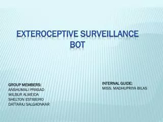
Surveillance Bot. Group 9 Charlie Grubbs Daniel Lanzone Mike Roosa Ryan Tochtermann. Overview. Goals. Motivation. To create a scalable all-terrain remote surveillance system with stabilization platform Audio detection capable of monitoring stereo sound levels Real-time video link

E N D
Surveillance Bot Group 9 Charlie Grubbs Daniel Lanzone Mike Roosa Ryan Tochtermann
Overview Goals Motivation To create a scalable all-terrain remote surveillance system with stabilization platform Audio detection capable of monitoring stereo sound levels Real-time video link Intuitive user-interface Robotics Systems Integration Scalability
Objectives • Vehicle can operate at a minimum of 4 MPH for at least 30 minutes • Camera stabilization platform capable of correction at a rate of 50 Hz • Pitch and roll correction of 45 deg. and a minimum of 60 deg/s correction rate • Stereo audio detection up to 10kHz • Wireless communication of at least 100 yards outdoors • Control via PC based GUI
Vehicle Chassis Overview • Capable of moving over semi-rugged terrain (unlevel, rocky, grassy) • Capable of overcoming ramped obstacles (< 35˚) • Moderate suspension for Z-axis stabilization • 4 mph • Low profile for stability
Vehicle Chassis : Suspension • Two passive shock absorbers on each front wheel • One passive shock absorber for rear axis
Vehicle Chassis: Motors Steering Motor • 50 RPM • 12 VDC rating • High torque gear box • Built-in potentiometer for position sensing Drive Motor • 2500 RPM • 12 VDC rating • Direct drive
Vehicle Chassis: Motor Controller • Two bidirectional motor ports • Driver: L298 Dual H-Bridge IC • Control: 3 digital pins per motor: 1 for enable, and 2 for motor direction • 6- 35 VDC Regulation • Up to 2A Output
Stabilization Requirements • Will provide pitch and roll stabilization for the mounted equipment (i.e. camera) • Correction rate of 50 Hz • 10 W peak power consumption (pitch and roll servos) • Platform does not change the CG significantly
Inertial Measurement Unit (IMU) • Sensitivity ±250, ±500, ±1000, and ±2000dps • Small form-factor (4x4x0.9mm QFN) • Low power consumption • Low drift
Stabilization Software • Controlled by ATMega328 • Microcontroller will be used to implement the PID and Kalman filter algorithms • Kalman filter will be used as sensor fusion between accelerometer and gyroscope
Hitec HS-5485 Servo motors • Controls: • Pitch • Roll • 3.3 V to 6 V • 60 degin .18 seconds (no load) • Mass: 59.82g • Dimensions: 40.39mm x 19.56mm x 37.59mm • 180 degree resolution
Wireless camera Camera requirements Cisco-Linksys Wireless-N 320x240 resolution IP camera 15 FPS 640x480 max resolution MJPEG stream Microphone 30 FPS 5V Barrel-jack input
Camera Testing • Camera tested at a peak bandwidth 1.2 Mbps with highest image quality setting and 30 FPS • Configured as an Ad-hoc network, the latency was reduced significantly
Overview • Stereo detection • Two microphones shock mounted to chassis, facing east and west • Two stage signal amplification chain • DSP on ATmega328 • Wireless communication via Xbee • User alerted via the GUI
Microphone Specs • Logitech desktop microphone • Generates peak of ~1.5mV • Modifications • Shielding
Analog Onboard Audio Signal Processing • Microphone connection to PCB • Amplifier LM386 • Two gain stages • Gain of 2500 • Small signal
GUI • Visual Design
Sound Level / Notification Correspondence Decibel Level Examples Table
SPL Input / Output Voltage Correspondence Gain Adj. Voltage (V) SPL Input (dB)
Sound Level / Notification Correspondence 0V to 0.353V Gain Adj. Voltage (V) Level 0 SPL Input (dB)
Sound Level / Notification Correspondence 0.353V to 1.061V Gain Adj. Voltage (V) Level 1 SPL Input (dB)
Sound Level / Notification Correspondence 1.061V to 3.535V Gain Adj. Voltage (V) Level 2 SPL Input (dB)
Sound Level / Notification Correspondence 3.353V Gain Adj. Voltage (V) Level 3 SPL Input (dB)
Microcontroller Interfacing • analogRead() • Maps input voltages from 0 V to 5 V • Will use full resolution of 4.8 mV (10 bit) • Software/Programming • Loop that constantly checks input voltage from microphone • Changes output based on notification level
Communications System Overview • Capable of reliable and accurate data transmission • Relatively long range (100+ yards) • Low power consumption • Relatively simple setup and configuration • Low cost
Communications System Overview • The goal is to create a network between the PC and the vehicle in order to send control and sensor data between them. • It will feature a PC-side and embedded-side system, each consisting of a wireless RF module and a regulated serial interface between the module and the PC or onboard microcontroller.
XBee Series 2 RF Modules Key Features: • 3.3V @ 40mA operation • Data rates up to 250 kb/s • 400 ft (133.33 yd) range Pros: • Long range • Low power consumption • Low cost Cons: • For Series 2 modules; difficult to configure for point-to-point communication Xbee Series 2 Module – 2mW Antenna Model
Embedded-Side Interfacing • Because the XBee operates at 3.3 V and the AtMega328 operates at 5 V, a voltage regulator is required for VCC input. • A level-shifting diode is also required on the Xbee’sData In line to account for this voltage difference. • Other pins are connected to the microcontroller accordingly.
Embedded-Side Development • The Arduino XBee Shield is a simple interface between wireless module and microcontroller • Takes care of all voltage regulation, I/O connections, and status LEDs • Still allows access to all other Arduino pins Development/Testing using Arduino’s XBee Shield
PC-Side Interfacing • An XBee Explorer USB will be used to connect the other XBee module to the PC. • The device uses an FT232RL USB to RS-232 serial UART to interface between the XBee and the PC. • Takes care of voltage regulation and I/O connections for easy development and testing. RS-232 to USB connection via XBee Explorer
Successes and Difficulties Difficulties: • Getting the Series 2 XBee modules to talk quickly and reliably. Solution: Module is configured to broadcast mode for mesh networks by default. Must be changed to have only one destination node every time it is powered up. Successes: • Established a reliable wireless network. • Sent and received messages between microcontroller and PC • Wireless drive control of surveillance vehicle for over 100 yards. • Sensor data acquired for over 100 yards.
Control Software Overview • Embedded-Side Software • Must receive user control data and respond accordingly • Must relay sensor data to PC-side software • PC-Side Software • Simple GUI for complete control and current status of surveillance vehicle • Must receive sensor data and display it in a simple format • Must transmit user control data quickly
PC-Side Software: GUI Features: • Centered image of IP webcam feed • Sound detection indicators on left and right side of image • Vehicle drive controls • Camera positioning controls • Enable/disable stabilization option Sketch of a desired GUI Layout
PC-Side Software: Processing IDE • High-compatibility with Arduino platform • Simple graphical user interface design • Useful libraries: • Controlp5 library for GUI components • Video library for webcam stream • Serial library for communications Sample GUI written in Processing
Embedded-Side Software • Will be programmed in the Arduino IDE • Will utilize the Serial library for read/write communications • Will have the following functionality: • Read input values and send control data to the motor controller • Write sensor data to the PC-side software to be displayed on the GUI