Download
1 / 22
220 likes | 339 Views
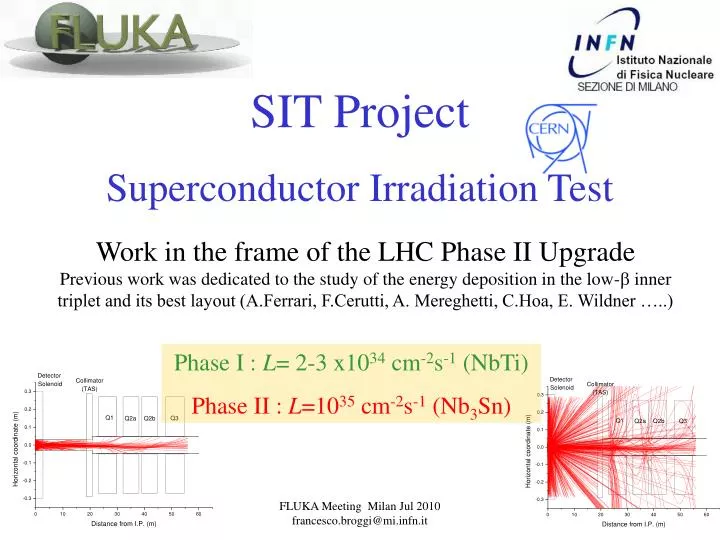
SIT Project Superconductor Irradiation Test. Work in the frame of the LHC Phase II Upgrade Previous work was dedicated to the study of the energy deposition in the low- b inner triplet and its best layout (A.Ferrari, F.Cerutti, A. Mereghetti, C.Hoa, E. Wildner …..).

E N D
SIT Project Superconductor Irradiation Test Work in the frame of the LHC Phase II Upgrade Previous work was dedicated to the study of the energy deposition in the low-b inner triplet and its best layout (A.Ferrari, F.Cerutti, A. Mereghetti, C.Hoa, E. Wildner …..) Phase I : L= 2-3 x1034 cm-2s-1 (NbTi) Phase II : L=1035 cm-2s-1 (Nb3Sn) FLUKA Meeting Milan Jul 2010 francesco.broggi@mi.infn.it
Outline • Why Irradiation tests ? • Beam needs • Beam availability • Geometry/energy deposition activation and cooling (no soldering) • Soldering (negative) effect • Next: Thermal analysis • DPA analysis
The magnetic elements close to the LHC IP will undergo to a heavy radiation load (At phase II it will be 10 times the the nominal one, being the Luminosity 10 times higher) Ways of reducing the radiation load are the optimization of the optics, larger aperture magnets (100-200 mm with Nb3Sn technology), liners, protections, ….
~1 MeV The neutron energy fully covers a wide interval, down to thermal energies E dNdE (part.coll.-1 cm-2) neutrons damage conductorphotons damage insulatorsprotons have lower effects ? Spectra in Q2a 100 … 200 MeV From F.Cerutti, A Mereghetti It is necessary to do irradiation tests on Nb3Sn cable samples, in order to predict the behaviour/degradation “spot” and old data about the radiation damage un Nb3Sn
From L. Bottura slides at EuCARD workshop on insulator irradiation, CERN, December 2, 2009
From L. Bottura slides at EuCARD workshop on insulator irradiation, CERN, December 2, 2009
From L. Bottura slides at EuCARD workshop on insulator irradiation, CERN, December 2, 2009
Beam Sources (with cryogenic irradiation facility) PROTONS : Cyclotron at Kurchatov Insitute • NEUTRONS: • Reactors (Atominstitut in Wien, TRIGA) • Secondary Neutrons from p on Be (at the cyclotron of the Kurchatov Institute)
p beam p on Be Ep = 30 MeV Spot size = 2 cm FWHM Be target (Cylinder) r = 5 cm, h = 2 cm 10runs with 106 particles each
p on Be integrated spectrum (over angles) “Double differential” spectrum Values already multiplied for the energy, to have directly the number of neutrons/proton
p on Be With 20 ma p current a total flux of 1.6x10¹² n/s will be avalilable (fw) from such a target Reactor fluxes ~ 1013 - 1014 n/cm2s Atominstitut reactor will provide n beam
Ti5 Nb3Sn cable SimpleGeo Plot The Sample Holder
Energy Deposition Ep = 30 MeV ; Spot size = 2 cm FWHM Cooling LHe, LN2, H2O (closer beam origin in case of LN2 and H2O) Cut-offs = 100 keV for hadrons, and 10 keV for electrons, positrons and photons Energy deposition (GeVpr-1) 10 runs with 107 particles each
Energy Deposition Maps LHe LN2 H2O The energy/power deposed in the sample holder is about 230 J/s (40% of the primary beam). The beam spot is larger than the sample holder bin dimensions = 1 x 1 x 1 mm3
Energy Deposition Maps LHe LN2 p beam H2O cable p beam origin bin dimensions = 0.1 x 0.5 x 0.5 mm3
Ti5 Nb3Sn cable Problem. The sample moves during the critical current measurements Solution (under discussion). Mechanically fix the Nb3Sn sample with a Sn-Pb soldering
target 30 MeV p beam Solution ? Solution (only proposed) : Fix the sample with a soldering Is it reliable ? The soldering composition is 60% Sn and 40% Pb. It is, on average, similar to Cu. As from literature the range of 30 MeV protons in Cu is 1.44 g/cm2 so it is 1.6 mm being 8.96 g/cm3 the Cu density
Energy Deposition Maps LHe LN2 p beam The energy deposition occurs in the soldering and not in the cable H2O cable p beam origin soldering bin dimensions = 0.1 x 0.5 x 0.5 mm3
Activation and Cooling Questions: Can be “used” such an object ? Are precautions needed ? What ?
Residual Nuclei Ti sample holder (lower part only) Soldering t=0 t=1h t=7d
Temperature increase (the irradiation must not melt the cable or the sample holder)Adiabatic Hypothesis Unphysical number The specific heat at 4 K is the crucial value The adiabatic hypothesis is not valid, so thermal conductivity and thermal exchange must be taken into account. Thermal model has been developed (F.Liberati), but a thermal analysis is necessary, to have most reliable evaluations.
What’s Next ? • Find mechanical solution better than the soldering • Thermal analysis (provide the adapted USRBIN output as ANSYS input) • Benchmarking of the simulations with the irradiation tests • DPA evaluation (FLUKA pre-release)