Download
1 / 28
280 likes | 424 Views
Modeling the YAGUAR Reactor Neutron Field and Detector Count Rates in the Direct a nn Measurement. Bret Crawford and the DIANNA Collaboration June 9, 2003. Direct Investigation Of a nn Association (DIANNA). Duke/TUNL NCSU/TUNL Gettysburg College. JINR ARRITP. nn-Scattering Length.

E N D
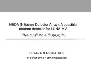
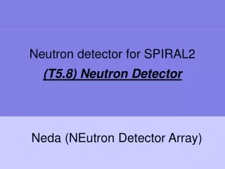
Modeling the YAGUAR Reactor Neutron Field and Detector Count Rates in the Direct ann Measurement Bret Crawford and the DIANNA Collaboration June 9, 2003
Direct Investigation Of ann Association (DIANNA) Duke/TUNL NCSU/TUNL Gettysburg College JINR ARRITP
nn-Scattering Length s= 4 ann2 as k 0 = ¼ s + ¾ t = ¼s = ann2
Charge Symmetry Breaking – 0.5 fm DaCSB 2.5 fm app = (-17.3 ± 0.8) fm ann = (-18.5 ± 0.3) fm ann = (-16.27 ± 0.40) fm Nagels et al. NUCL. PHY B147 (1979) 189. Howell et al. PHYS LETT B444 (1998) 252. González Trotter et al. PHYS REV LETT 83 (1999) 3788. Huhn et al. PHYS REV C 63 (2001) 014003.
YAGUAR ReactorAll-Russian Research Institute of Technical Physics Snezhinsk, Russia
YAGUAR Reactor • Pulsed reactor with high instantaneous flux • Annular design with open through-channel (nn-cavity) • 90% enriched 235U-salt/water solution • Energy per pulse – 30 MJ • Pulse duration – 900ms • Fluency – 1.7x10¹⁵ /cm2 • Flux – 1x10¹⁸ /cm2/s • Neutron density – 1x10¹³ /cm3
40 cm absorber The Experiment • Neutron collisions take place in reactor through-channel • Neutrons are detected 12 m below detector • snn determined from detector counts and known flux • Expect ~150 counts/pulse • Background (non-collision neutrons at detector) is an issue Reactor Moderator collimators shielding shielding 12 m detector
40 cm The Experiment To absorber • Collisions take place in reactor through-channel Reactor with Moderator sleeve Through Channel 40 cm Shielding To detector
40 cm The Experiment To absorber • Collisions take place in reactor through-channel • Absorber prevents backscattered neutrons from reaching detector Reactor with Moderator sleeve 40 cm Shielding To detector
40 cm The Experiment To absorber • Collisions take place in reactor through-channel • Absorber prevents backscattered neutrons from reaching detector • Collimation prevents direct path from moderator to detector and wall scattered neutrons Reactor with Moderator sleeve 40 cm Shielding To detector
40 cm The Experiment To absorber • Collisions take place in reactor through-channel • Absorber prevents backscattered neutrons from reaching detector • Collimation prevents direct path from moderator to detector and wall scattered neutrons • Shielding absorbs neutrons from reactor Reactor with Moderator sleeve 40 cm Shielding To detector
Detector Count Rates and the Need for Modeling • Detector Counts • n-Production Rate along z-axis • MCNP and Analytic Modeling to determine cavP Spatial, angular, energy, time distributions
MCNP Modeling • Modeling of Yaguar reactor core with moderator sleeve • Neutron Field Distributions in through-channel
2 y = 2 c o s ( d e l t a ) e l c i t r 1 . 5 a p / y l l a t d 1 e z i l a m r o 0 . 5 N 0 0 0 . 2 0 . 4 0 . 6 0 . 8 1 1 - c o s ( d e l t a ) MCNP Modeling Spatial Distribution Angular Distribution* cos(p z/La)cos(d) + A cos2(d); A=0 *Amaldi and Fermi, PHYS REV50 (1936) 899-928. 0 <A < 3
MCNP Modeling Energy Distribution Maxwellian (E0=26 meV) with epithermal tail (1/E)
Geometry for Analytic Calculations • Neutrons from source points Q1 and Q2 collide at point field point P
Neutron Density and Collision Rate Dickinson, Lent, Bowman, Report UCRL-50848 (Livermore, 1970)
Production Rate in Direction of Detector Isotropic scattering in CM-frame Pz =2Nnn/4p (neutrons/steradian) Anisotropic scattering in Lab-frame g = angle between vcm and z-axis
Production Rate • Small r-dependence • Small dependence on angular distribution parameter A
Calculation of cavP • Yaguar Anisotropic Case Monovelocity cavP=0.78 Maxwellian dist. cavP=0.84 Angular, spatial, energy (Maxwellian only) distributions have been included. • Isotropic, monovelocity ideal gas
40 cm To absorber Reactor with Moderator sleeve 40 cm Shielding To detector Neutron Background Sources of background • Thermals direct from moderator sleeve Collimation • Wall scattered thermals Collimation • Backscattered neutrons Absorber • Scattering from residual gas 10-6 Torr 2% background • Reactor neutrons……
Neutron Background Main source is reactor vessel • Lots of Shielding!! – 12m of concrete, borated water,… • Early fast neutrons – Time of Flight can separate collided thermals from initial burst of fast neutrons • Delayed fast neutrons – ToF is of no use, rely on shielding Vary Flux: Reactor background ~F, Neutron signal ~F2 Two-fold approach • Two separate teams are modeling shielding effectiveness • Experiments in fall ‘03 to understand background characteristics under shielding beneath reactor
Status and Future† • Neutron-field and count-rate modeling near completion • Shielding modeling underway (preliminary modeling of delayed fast neutrons for simplified geometry shows background at the 5% level*) • Experimental background measurements planned for Fall ’03 • Finalize geometry Winter ’04 †W.I. Furman, et al., J. Phys. G: Nucl. Part. Phys. 28 (2002) 2627-2641. *G.P. Gueorguiev, et. al, Accel. App. in a Nucl. Ren., AccApp’03, June 1-3, 2003, San Diego.
DIANNA Collaboration JINR (Dubna, Russia): W. I. Furman, E. V. Lychagin, A. Yu. Muzichka, G. V. Nekhaev, Yu. V. Safronov, A. V. Strelkov, E. I. Sharapov, V. N. Shvetsov ARRITP (Snezhinsk, Russia): B. G. Levakov, V. I. Litvin, A. E. Lyzhin, E. P. Magda TUNL (Durham, NC): C. R. Howell, G. E. Mitchell, W. Tornow Gettysburg College (G’burg, PA): B. E. Crawford, S. L. Stephenson W.I. Furman, et al., J. Phys. G: Nucl. Part. Phys. 28 (2002) 2627-2641.
Review article by I. Slaus et al., Physics Reports173 (1989) “..in order to obtain relevant information on CSB and particularly on explicit quark contributions, it is necessary to improve the accuracy [of effective range parameters], i.e., ann should be known to ± 0.2 fm…” Four suggestions for further research: “(1) Perform a direct n-n scattering measurement.”
Shielding Modeling • Using MCNP with energy-dependent weight windows (WWE) variance reduction • Simplified geometry Preliminary Results • Fission neutrons with Einital<2.5MeV do not contribute • Some spatial separation between background and signal neutrons at detector • Variance reduction techniques are working but are challenging for complicated geometries. • 5% background from delayed fast neutrons is reasonable G.P. Gueorguiev, et. al, Accel. App. in a Nucl. Ren., AccApp’03, June 1-3, 2003, San Diego.
Shielding Modeling Energy Spectrum at Detector Radial Distribution of detector events G.P. Gueorguiev, et. al, Accel. App. in a Nucl. Ren., AccApp’03, June 1-3, 2003, San Diego.