Download
1 / 44
450 likes | 602 Views
Design, Fabrication and Characterization of a MEMS Thermal Displacement Sensor for a Closed Loop Embedded MEMS Precision Stage (CLEMPS). Richard Hogervorst. March 16, 2010. Content. Background Principle of thermal sensing Existing thermal displacement sensor Concept designs

E N D
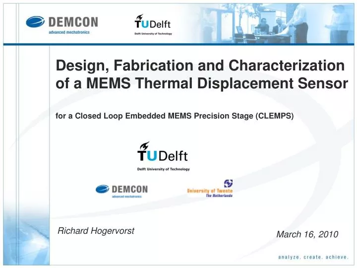
Design, Fabrication and Characterization of a MEMS Thermal Displacement Sensorfor a Closed Loop Embedded MEMS Precision Stage (CLEMPS) Richard Hogervorst March 16, 2010
Content Background Principle of thermal sensing Existing thermal displacement sensor Concept designs Fabricated devices Modelling sensor behaviour Experimental characterization Conclusions & recommendations
Background • CLEMPS project: • Designing a Closed Loop Embedded MEMS Precision Stage • Sensors, actuators and control integrated in small footprint • 10-nm repeatable accuracy over a range of 100 micron • Subsidized by Point One • Need for embedded MEMS stages • Many possible applications • Collaboration: Integrated MEMS-sensors: - Capacitive - Thermal Objective: Evaluation of the feasibility and performance of thermal displacement sensing by design, fabrication, modelling and experimental characterization of a proof-of-concept.
Background • CLEMPS project: • Designing a Closed Loop Embedded MEMS Precision Stage • Sensors, actuators and control integrated in small footprint • 10-nm repeatable accuracy over a range of 100 μm • Subsidized by Point One • Need for embedded MEMS stages • Many possible applications • Collaboration: Integrated MEMS-sensors: - Capacitive - Thermal Objective: Evaluation of the feasibility and performance of thermal displacement sensing by design, fabrication, modelling and experimental characterization of a proof-of-concept.
Principle of thermal sensing • Resistive heating using fixed supply voltage • Cooling efficiency depends on varying stage overlap • Displacement is determined from resistance (~current) • Differential measurement reduces environmental influences • On small scale heat transfer is dominated by thermal conduction
Existing thermal displacement sensor (TDS) • Mark A Lantz, Gerd K Binnig, IBM Zurich Research Lab • Application: • Millipede project: High Density Data storage using thermo-mechanical writing/reading • Performance: • Range: ±50 μm • Resolution: 2.1 nm • Bandwidth: 10 kHz • Drifting • Characteristics: • Power: 10 mW • Differential measurement • No integrated stage • Complex fabrication High resistive region
Concept designs • Design I: Radiative TDS for vacuum applications • Design II: Stacked TDS • Design III: In-plane TDS using localized resistance • Design IV: In-plane TDS without localized resistance: • Lower sensitivity • High power dissipation (~90 mW) • Simple and reliable fabrication • Design V: In-plane thermal comb displacement sensor • Stage Bond pads Position dependent overlap
Concept designs • Design I: Radiative TDS for vacuum applications • Design II: Stacked TDS • Design III: In-plane TDS using localized resistance • Design IV: In-plane TDS without localized resistance • Design V: In-plane thermal comb displacement sensor: • Very high sensitivity to displacement • Very high power dissipation (~200 mW) • Simple fabrication • Large footprint • Stage Stage overlap Bond pads
Fabricated devices • Design I: Radiative TDS for vacuum applications • Design II: Stacked TDS • Design III: In-plane TDS using localized resistance • Design IV: In-plane TDS without localized resistance • Design V: In-plane thermal comb displacement sensor • Fabricated: designs IV and V: • Compatibility with SOI-fabrication process • Integration with stage • Available wafers:
Fabricated devices • Design I: Radiative TDS for vacuum applications • Design II: Stacked TDS • Design III: In-plane TDS using localized resistance • Design IV: In-plane TDS without localized resistance • Design V: In-plane thermal comb displacement sensor • Fabricated: designs IV and V: • Compatibility with SOI-fabrication process • Integration with stage • Available wafers:
Fabricated devices Thermal displacement sensors integrated with actuated stage (± 30 μm) 2 mm Comb drive Comb drive Suspensions Suspensions • Stage 3 mm
Fabricated devices • Stage Uactuation = 84V 50 μm Heater 1 Heater 2 Compensation structure Bondpad Bondpad • Basic geometry for fabricated sensors • Minimum reliable feature width of 3 μm • Measurement range of 60 μm • Leg length of 100 μm
Modelling sensor behaviour • Thermo-electrical FEM in COMSOL • Insight in thermal behaviour by using multi-physical modelling • Thermal conductivity of air • Thermal conductivity of silicon • Electrical resistivity of boron doped silicon (n0 = 5e18 cm-3)
Modelling sensor behaviour 2D topview of both heaters and surrounding structures
Modelling sensor behaviour 2D topview of both heaters and surrounding structures
Modelling sensor behaviour 305 K 309 K • Efficient stage cooling • Conduction through 1 μm air-gap to substrate • Large surface area • Good thermal spread 293 K
Modelling sensor behaviour • Efficient bond pad cooling • Conduction through 1 μm oxide to substrate • Large surface area • Good thermal spread 308 K 293 K
Modelling sensor behaviour • Heater temperature • distribution 876 K • Maximum heater temperatures: 876K – 793K • Non-uniformity of temperature along sensing range: 50K – 30K. 293 K
Modelling sensor behaviour • Heat losses • Bond pads ~35 mW • Substrate ~10 mW • Rest ~10 mW Heat flux towards the stage 7e6 W/m2 Ptotal ~100 mW ~2 mW ~11.5 mW 0
Experimental characterization • Optical characterization of stage mechanics • Derive relation between actuator voltage and stage displacement • Electronics • Current-to-voltage amplification (560 mV/mA) • Differential voltage amplification (16 mV/mV) • Heater voltage (9V) • High voltage actuation (85V to obtain 25 μm displacement) • Filters (30 Hz cut-off) • Recording of signals (xPC) • Actuation voltage • Individual heater currents • Differential current (Sensor output)
Experimental characterization • Individual heater response Heater 1 Heater 2
Experimental characterization • Individual heater response Heater 2 Heater 1
Experimental characterization • Individual heater response Heater 1 Ptotal /2 Heater 2
Experimental characterization • Differential measurement response • Performance • Offset: 1.77 V • Sensitivity: 106.1 mV/μm (12.6 μA/μm) • Noise (1-sigma): 0.37 mV (3.5 nm) • Nonlinearity: ±400 nm
Experimental characterization • Measurement sensitivity • Measurement sensitivity varies between 11.1 μA/μm and 13.1 μA/μm • Good repeatability of average sensitivity: ±1% • -3dB Bandwidth: 1 kHz
Experimental characterization • Sensor drift: 0.4 μA (32 nm) in 32 hours • Stage in neutral position • Normal laboratory conditions • After 1 week of run-in • Stability of environmental conditions: Especially influence of temperature • Deterioration of the heaters: Varying resistance in time • Start-up of the sensor: 10 min to reach thermal equilibrium within 10 nm
Conclusions & Recommendations • Principle of thermal displacement sensing works, and behaves as expected! • Obtained resolution is 3.5 nm (1-σ noise) over a range of 50 μm.
Conclusions & Recommendations • Principle of thermal displacement sensing works, and behaves as expected! • Obtained resolution is 3.5 nm (1-σ noise) over a range of 50 μm. Summary of performances for designs IV and V:
Conclusions & Recommendations • Principle of thermal displacement sensing works, and behaves as expected! • Obtained resolution is 3.5 nm (1-σ noise) over a range of 50 μm. • Limitations of thermal displacement sensing: • Run-in time • Heat generation • Sensor drift
Conclusions & Recommendations • Principle of thermal displacement sensing works, and behaves as expected! • Obtained resolution is 3.5 nm (1-σ noise) over a range of 50 μm. • Limitations of thermal displacement sensing: • Run-in time • Heat generation • Sensor drift • Investigation of its physical principles • Reduce drift by compensation
Conclusions & Recommendations • Principle of thermal displacement sensing works, and behaves as expected! • Obtained resolution is 3.5 nm (1-σ noise) over a range of 50 μm. • Limitations of thermal displacement sensing: • Run-in time • Heat generation • Sensor drift • Investigation of its physical principles • Reduce drift by compensation • Design IV has potential for CLEMPS project: • Good performance • Difficult to provide multi-DOF sensing • Reliable fabrication and integration for many applications
Stage 50 μm Heater 1 Heater 2 Bondpad Bondpad Questions & Discussion
Concept designs • Design I: Radiative TDS for vacuum applications: • High temperatures • Insufficient absorbtion of radiation • Complex fabrication
Concept designs • Design I: Radiative TDS for vacuum applications • Design II: Stacked TDS: • High sensitivity to displacement • Low power dissipation (~10 mW) • Complex fabrication
Concept designs • Design I: Radiative TDS for vacuum applications • Design II: Stacked TDS • Design III: In-plane TDS using localized resistance: • Lower sensitivity • High power dissipation (~60 mW) • Feasibility questionable • Stage • Gold layer (design III only) • + Localize sensing and heating • - High current density • - Difficult alignment Bond pads Position dependent overlap
Modelling sensor behaviour Thermal deformation (x20) 150 nm • Small gap variations (between 3 – 5%) • Increased sensitivity in middle region 0 nm y-displacement
Conclusions & Recommendations • Principle of thermal displacement sensing works, and behaves as expected! • Obtained resolution is 3.5 nm (1-σnoise) over a range of 50 μm. • Limitations of thermal displacement sensing: • Run-in time • Power dissipation • Sensor drift • Investigation of its physical principles • Reduce drift by compensation • Design IV has potential for CLEMPS project: • Sufficient performance • Further geometry optimization using models • Reduce electronic noise • Reliable fabrication and integration for many applications • Difficult to provide multi-DOF sensing • Mechanically decouple movements • Alternative design II
Add reference sensor • Second pair of heaters having fixed overlap
Frequency behaviour • Stage dynamics + sensor dynamics