Download
1 / 23
230 likes | 486 Views
Lab 9. Simple processor. 實驗目的: 了解 CPU 的運作原理 及 Datapath , Control Unit 的 RTL 設計觀念 實驗內容: 實作一簡易 CPU ,理解 Control Unit 的 控制訊號 和 Datapath 資料流動的原理. RTL 設計. Datapath. 資料路徑 output. 資料路徑 input. 控制訊號. Control Unit. 控制單元 input. 控制單元 output. D.P. 資料. CPU 週期. fetch. execute. decode.

E N D
Lab 9 Simple processor
實驗目的:了解CPU的運作原理 及 Datapath , Control Unit 的RTL設計觀念 • 實驗內容:實作一簡易CPU,理解Control Unit的控制訊號 和 Datapath 資料流動的原理
RTL設計 Datapath 資料路徑output 資料路徑input 控制訊號 Control Unit 控制單元 input 控制單元 output D.P.資料
CPU 週期 fetch execute decode • Fetch:從Memory中取得instruction • Decode:將instruction解碼所屬分類 • Execute:再依opcode細分,來執行不同的指令運作及儲存結果(執行週期不盡相同) • 以上即為CPU反覆的循環動作
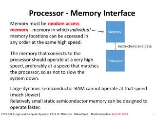
Instructions & Data In mvi 指令的 #Data, 是在下一次的Data In讀入16 bits的資料
Finite State Machine State0 State1 State2 State3 State4 State5 State6
Lab 9 process 架構圖 (part 1) R0 R1 R2 R3 R4 R5 R6 R7 A AddSub DIN G Multiplexers Bus IR Control Unit Done Run Reset
mv R0, R5 -State 0< IR in > R0 R1 R2 R3 R4 R5 R6 R7 A AddSub DIN G Multiplexers Bus IR Control Unit Done Run Reset
mv R0, R5 -State 1< Ry out , Rx in , Done > R0 R1 R2 R3 R4 R5 R6 R7 A AddSub DIN G Multiplexers Bus IR Control Unit Done Run Reset
mvi R0, #Data -State 0< IR in > R0 R1 R2 R3 R4 R5 R6 R7 A AddSub DIN G Multiplexers Bus IR Control Unit Done Run Reset
mvi R0, #Data -State 1< DIN out , Rx in , Done > R0 R1 R2 R3 R4 R5 R6 R7 A AddSub DIN G Multiplexers Bus IR Control Unit Done Run Reset
add R0, R1 -State 0< IR in > R0 R1 R2 R3 R4 R5 R6 R7 A AddSub DIN G Multiplexers Bus IR Control Unit Done Run Reset
add R0, R1 -State 1< R0 out , A in > R0 R1 R2 R3 R4 R5 R6 R7 A AddSub DIN G Multiplexers Bus IR Control Unit Done Run Reset
add R0, R1 -State 2< R1 out , G in > R0 R1 R2 R3 R4 R5 R6 R7 A AddSub DIN G Multiplexers Bus IR Control Unit Done Run Reset
add R0, R1 -State 3< G out , R0 in , Done > R0 R1 R2 R3 R4 R5 R6 R7 A AddSub DIN G Multiplexers Bus IR Control Unit Done Run Reset
Part 1 Processor 模擬圖 (左半) mvi R0,#05h mv R1,R0 add R0,R1
Part 1 Processor 模擬圖 (右半) sub R0,R0 sub R3,R1 mvi R3,#1F0Eh
8 8 8 8 8 8 8 8 DE2 Control (part1) 七段顯示器 7 6 5 4 3 2 1 0 HEX6 = IR值 HEX5 = State HEX4 = RegNumber HEX3~0 = Reg Value SW 17 = Run Reset = KEY 0 Clock = KEY 1 切換Reg= KEY 3
Lab9 part 2 外接Memory示意圖 MClock:控制Memory讀取下一個指令的時脈 PClock:Processor的時脈 Run:控制processor的開關 Resetn:控制reset
8 8 8 8 8 8 8 8 DE2 Control (part2) 七段顯示器 7 6 5 4 3 2 1 0 HEX6 = IR值 HEX5 = State HEX4 = RegNumber HEX3~0 = Reg Value SW 17 = Run Reset = KEY 0 Mclock = KEY 1 Pclock = KEY 2 切換Reg= KEY 3
Initial ROM value & Download Demo 註1:紅色字為 Rx更動後的值 註2:青綠色字為 mvi 的 #D值