Download
1 / 7
140 likes | 593 Views
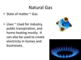
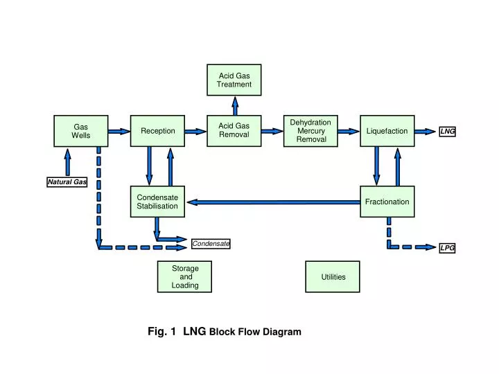
Acid Gas. Treatment. Dehydration. Gas. Acid Gas. Mercury. Wells. Removal. Removal. Condensate. Stabilisation. Storage. and. Loading. Reception. Liquefaction. LNG. Natural Gas. Fractionation. Condensate. LPG. Utilities. Fig. 1 LNG Block Flow Diagram. Pure Refrigerant.

E N D
Acid Gas Treatment Dehydration Gas Acid Gas Mercury Wells Removal Removal Condensate Stabilisation Storage and Loading Reception Liquefaction LNG Natural Gas Fractionation Condensate LPG Utilities Fig. 1 LNG Block Flow Diagram g:\depts\152\g\9997
Pure Refrigerant Natural gas Cooling Curve Temperature Refrigerant Cooling Curve MixedRefrigerant MixedRefrigerant Heat Fig. 2 Typical Natural Gas / Refrigerant Cooling Curves g:\depts\152\g\9997
Expander To Furnace C1 ScrubColumn AcidGas LNGto Storage AmineUnit G MercuryRemovalUnit Generator SourFeedGas HHP C3 HPC3 MPC3 LPC3 DehydrationUnit NGL Reinjection HP Fuel Gas HP FuelGas C3 C2 EndFlash Gas Compressor M MainCryogenicExchanger HydrocarbonCondensate toStorage Fractionation LP C3 C3 Compressor MP C3 M GT MR Compressor HP C3 HHP C3 M GT HHP C3 HP C3 MP C3 LP C3 Multicomponent RefrigerantSystem N2 C1 C2 C3 Propane Precooling RefrigerantMake-up Fig. 3 APCI Propane Precooled Mixed Refrigerant Process (Typical) g:\depts\152\g\9997
TreatedGas LNG Propane Ethane Methane Fig. 4 Phillips Optimised Cascade Process g:\depts\152\g\9997
Process Gas LNG Fig. 5 Black & Veatch PRICO Process
Process Gas Precooling Liquefaction Subcooling LNG Fig. 6 Statoil . Linde Mixed Fluid Cascade Process (MFCP)
Process Gas Precooling Liquefaction LNG Fig. 7 Axens Liquefin Process