Download
1 / 13
130 likes | 152 Views
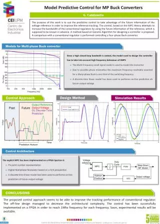
Study on electrothermal model of inductor for boost converters, addressing nonlinearity and self-heating effects. Results and conclusions discussed.

E N D
Application of the Electrothermal Average Inductor Model for Analyses of Boost Converters Krzysztof Górecki, Janusz Zarębski, Kalina Detka Gdynia Maritime University Department of Marine Electronics
Outline • Introduction • The average electrothermal model of the diode-transistor switch • The average electrothermal model of the inductor • Results of calculations and measurements • Conclusions
Introduction (1) • The boost converter is frequently used in switched-mode power supplies. • The important parts of this converter are semiconductor devices and an inductor with the ferromagnetic core. • In literature the properties of this circuit are analyzed, but the consideration focused only on semiconductor devices ignoring properties of magnetic elements. • In previous authors papers it is shown, that the nonlinearity dependence L(i) significantly influences the course of characteristics of the considered converter. • In the cited papers, in order to calculate the characteristics of dc-dc converters the classical transient analysis method is used. • The analysis is time consuming, and there are often problems to obtain convergence of computations. • During dc-dc converters operation the internal components temperature rises due to a self-heating phenomenon.
Introduction (2) • To take into account this phenomenon in the computer analysis, special electrothermal models are required. • The average electrothermal model of the diode – transistor switch for SPICE is proposed, but in this model non-linearity of the inductor characteristics and self-heating in this element are omitted. • In this paper the average electrothermal model of the inductor dedicated to the electrothermal analysis of dc-dc converters is proposed. • This model takes into account magnetic and thermal phenomena in the inductor and power losses in the core and in the winding. • The model is used to calculate non-isothermal characteristics of the boost converter.
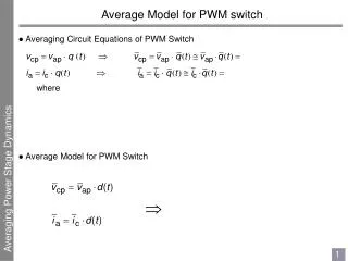
The average electrothermal model of the diode-transistor switch • Control voltage sources Et and Er represent the unipolar transistor, connected to terminals 1, 2 and 5 • The diode (between the terminals 3 and 4) is represented by the controlled current source Gd. • The auxiliary circuit is used to determine the mode of dc – dc converter (CCM or DCM) including the considered switch. • The aided block model the temperature changes of transistor resistance RON, series diode resistance RD and voltage UD on the forward biased p-n junction. • The internal diode and transistor temperature are calculated in the thermal model.
The average electrothermal model of the inductor • The average electrothermal model of the inductor refers to an average value of voltage and current in the circuit, instead of the transient values . • The values of all the above mentioned quantities can be determined by the electrothermal model of the inductor • Terminals A and B are the terminals of the inductor. • Terminal L - the voltage corresponding to the inductor inductance, • Terminal TU - the temperature of the inductor winding, • Terminal TR - the temperature of the inductor core.
The average electrothermal model of the inductor (2) • In the main circuit: • the voltage source VL with zero output voltage monitors the current of the inductor, • the resistor RS0 represents the winding resistance of the inductor for the direct current at the reference temperature T0 • the controlled voltage source ERS describes the influence of temperature and losses of the inductor series resistance. • the controlled voltage source ERN models the skin effect phenomenon • In the auxiliary blockthe controlled voltage sources are used to calculate the value of: • the magnetic force H, • flux density B, • Bsat saturation flux density • the auxiliary value C. • The thermal model allows calculating an excess of the core TR and winding TU temperature above the ambient temperature Ta.
Results of calculations and measurements • The average electrothermal model of the inductor is used to calculate the characteristics of the boost converter, • the inductor L containing 27 turns of enamel copper wire of the diameter of 0.8 mm wound on a toroidal ferrite core RTF25x15x10 made of F867 material. • The considered circuit is excited by the DC voltage equal to 12 V, the frequency of the control signal is f = 50 kHz.
Results of calculations and measurements (2) • curves a - results of analyses obtained using average electrothermal models of the diode-transistor switch and the inductor, • curves b – the results obtained using the average electrothermal model of the diode-transistor switch and the linear inductor model without losses, • curves c - the results of analyses using isothermal models of considered devices, • curves d - the results of the transient analysis obtained using the electrothermal models of the transistor, the diode and the inductor.
Results of calculations and measurements (3) • It is easy to notice that in the considered range of load resistance the boost converter operates in both CCM and DCM modes. • Taking into account non-linearity of L(i) caused the shifts of the boundary between CCM and DCM mode towards bigger values of load resistance R0. • In the range of small values of R0 it can be seen that using the classical model without losses allows obtaining the constant output voltage Uwy and watt-hour efficiency. • From both the considered models the increasing dependences Uwy(R0) and (R0) are obtained, • Taking into account non-linearity of the inductor model reduces the converter output voltage and watt-hour efficiency. • It is worth noticing, that taking into account the inductor non-linearities and losses in the inductor causes the reduction of 50% in the output voltage, and the watt-hour efficiency - as much as 60%.
Results of calculations and measurements (4) • The considered dependences are decreasing functions. • For the high resistance R0, the core temperature is higher than the winding temperature and for the small resistance R0 the winding temperature achieves the higher value. • The computations time for the presented characteristics using average electrothermal models was about a ten miliseconds, whereas the determination of these characteristics by the transient electrothermal model takes several hours.
Conclusions • The paper presents the average electrothermal model of the inductor dedicated to determine non-isothermal characteristics of dc-dc converters using SPICE. • The proposed model takes into account the dependence of inductance and series resistance on: • the inductor current, • frequency, • temperature • inductor construction parameters • parameters of the core. • The results of computations show that taking into account in the presented model the physical phenomenon clearly affect characteristics of the considered circuit • In particular, the shift of the boundary between CCM and DCM mode towards higher values of R0 resistance is observed.
Conclusions (2) • The output voltage and watt-hour efficiency of the boost converter in the range of small values of R0 decrease. • The modified model also allows the computation of the core and winding temperature. • Simultaneously, the time needed to compute the non-isothermal characteristics of the considered converter is much shorter than using the classical transient analysis and the electrothermal model of the inductor.