Download
1 / 21
210 likes | 306 Views
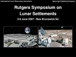
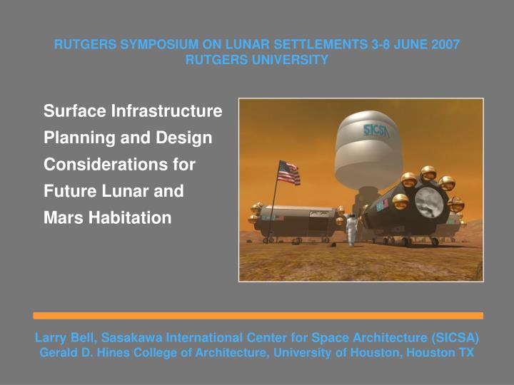
RUTGERS SYMPOSIUM ON LUNAR SETTLEMENTS 3-8 JUNE 2007 RUTGERS UNIVERSITY. Surface Infrastructure Planning and Design Considerations for Future Lunar and Mars Habitation. Heavy Lift Vehicles (HLVs) with capabilities to launch payloads approaching 100MT and 7 meter diameter

E N D
RUTGERS SYMPOSIUM ON LUNAR SETTLEMENTS 3-8 JUNE 2007 RUTGERS UNIVERSITY Surface Infrastructure Planning and Design Considerations for Future Lunar and Mars Habitation
Heavy Lift Vehicles (HLVs) with capabilities to launch payloads approaching 100MT and 7 meter diameter Approaches that utilize Medium Lift Vehicles (MLVs) with capacities ranging from about 15MT to somewhat less than 100MT Launch Systems
Typical Lander Concept SICSA Lander Concept Lander Considerations
Conventional module Telescopic module Vertical module with a spherical inflatable section Module Options
A triangular pattern scheme affords certain advantages and disadvantages: Pros: A relatively compact configuration footprint at the entry airlock level can minimize the area for site surface preparation if required. Loop egress is achieved with three modules. Con: May be more difficult to position/ assemble. A rectilinear scheme also offers advantages/ disadvantages: Pros: Greater spacing between berthing locations affords more useful wall/ equipment space. Con: Larger footprint for good site selection and/ or surface preparation. 4 modules are needed for loop egress. Vertical Module Configurations
The triangular scheme offers advantages and disadvantages: Pros: A very compact footprint around the inflatable module support bases to minimize site surface preparation requirements. Loop egress is achieved with 3 inflatable modules. Con: May be more difficult to assemble. The cruciform scheme also offers advantages and disadvantages: Pros: The deployment footprint around the horizontal module is quite small, limiting site preparation. The scheme can begin as a cruciform and evolve into a closed-loop plan. Con: Dual egress is not achieved until 4 modules are in place. Combination Configurations
Space/Launch Efficiency Configuration Comparisons
Emergency Egress Configuration Comparisons
Module Commonality Configuration Comparisons
Evolutionary Growth Configuration Comparisons
Surface Positioning Configuration Comparisons
Sleeping/Private Partitions Bed and storage Table Chair Shelves Privacy curtains Inflatable Upper Level Plan
Labs and Crew Workstations Glovebox Sample Photography Lab’s Workstation Experiment Tanks Sink/Refrigerator/ Freezer Fabric Storage Inflatable Second Level Plan
Orbital satellite imaging and unmanned precursor surface surveys should be undertaken to determine safe landing locations with appropriate terrain characteristics for base development. Robotic surface investigation and mapping rovers can determine optimized routings between landing and operational locations and deploy beacons. Automated survey/mapping rovers can later work in conjunction with rovers used for power cable deployment and cargo/human transport. Landing sites must be located at sufficient distances from habitats and other sensitive areas. Use of tethered landers can greatly reduce or avoid projectile hazards. RTGs or other power systems that produce radiation safety hazards must be located at a safe distance away from habitable facilities.. Site Development Considerations