Download
1 / 25
320 likes | 642 Views
AIDA - Academia meets Industry: Advanced interconnections for chip packaging in future detectors INFN Laboratori Nazionali di Frascati , 8-9/4/2013. Maria Giuseppina Bisogni University and INFN Pisa. Medical Imaging. Medical Imaging Today. Different Points of view. Medical point of view

E N D
AIDA - Academia meets Industry: Advanced interconnections for chip packaging in future detectors INFN LaboratoriNazionali di Frascati, 8-9/4/2013 Maria Giuseppina Bisogni University and INFN Pisa Medical Imaging
Different Points of view • Medical point of view • Application driven • Diagnosis or intervention • Morphological/functional/combined imaging • Parameter requirements (size, speed, spatial and contrast resolution, dose..) • Workflow • Physical point of view • Technology driven • Wavelength (X-rays, gamma rays, Visible light, NIR, Terahertz…) • Feasibility determined by available sources, materials, electronics, computing power And the economical point of view…
RadiologicalImaging General radiography Angiography Digital Subtraction Angiography (DSA) Mammography Computed Tomography (CT) Cardiology (fluoroscopy)
Digital Radiography Today • aSi:H Flat Panels technology firstly introduced in early ‘90s • First devices commercially available in in 2000 (GE Senographe) • State-of-the-art X-ray imaging is done with flat-panel detectors (aSi:H or aSe, TFT read-out)
Single Photon Counting (SPC) Systems • Noise suppression • Higher SNR or lower dose • Low event rate applications • Linear and wide dynamic range • Limited by counter saturation • Energy discrimination • Compton events rejection • Color Imaging • “Energy weighting” suppression • Low energy photons weight less than high energy ones in integrating systems • In SPC systems all photons have same weight • Edge-on Si strips • Hybrid pixels (MEDIPIX family)
First SPC commercial mammographicsystem SectraMicroDoseTM Now Philips MicroDose Mammography • Si strip detectors, 768 strips, 50 mm pitch, 21 detector rows • slight fan-out (to compensate beam divergence), 2 cm long • 500 mm thick • “quasi” edge-on (4º- 4.5º tilt angle) • ~90% efficiency @ 30 keV • ASIC: • 128 channels • counting rate/pixel: >1 MHz
Detective Quantum Efficiency M. Lundqvist et al., “Evaluation of a Photon-Counting X-Ray Imaging System”, IEEE Trans.Nucl.Sci. 48 (4), August 2001 • DQE describes how the Signal to Noise Ratio varies across the imaging system stages. • It depends on the frequency through the MTF and the NPS, both frequency functions. • At zero frequency, DQE(0) depends on the detection efficiency and on the image variance
Computed Tomography Today 1 3 2 z 4 16 x 0.75 mm 4 x 1.5 mm 4 x 1.5 mm Gd2O2S scintillator on photodiodes Courtesy of W. Kalender, U. Erlangen
Benefits of SPC in CT Low Dose CT Experimental validation of photon counting vs. conventional CT acquisition. The impact of “zero electronic noise” is apparent in ultra-low dose CT acquisitions. At high doses the “pile-up” effect makes counting individual photons difficult and lowers efficiency of photon counting detector. Color Imaging Photon Counting Prototype Clinical Study: Full FOV abdominal imaging. Improvements in material decomposition allow for Z-map images that are color coded according to tissue atomic number. Efficient energy separation allows for true mono-energetic images. ByTiborDuliskovich, MD, Medical Director CT, GE Healthcare “Photon Counting: A New CT Technology Just Over the Horizon”, 2011
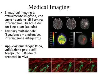
Future challenges in medical imaging PAST PRESENT FUTURE XX century XXI century “ A visual representation, characterization, and quantification of biological processes at the cellular and sub-cellular levels within intact living organisms.” SanjivS.Gambhir 14
Combining morphology and function Nuclear medicine imaging techniques (PET and SPECT) and X-ray radiology are intrinsically complementary. CT PET PET/CT A PET scan reveals areas of abnormal activity but the exact location is unknown A CT image precisely displays the body's anatomy but does not reveal the body's functional chemistry The information is combined 15
“PET-CT is a technical evolution that has led to a medical revolution” J.Czernin, UCLA • New detectors (materials, geometries) • 3D Acquisitions • Faster electronics • New reconstruction algorithms • High performance CT systems First PET/CT (1998) CTI PET Systems (now Siemens)
New whole-body imaging procedures allow comprehensive imaging examinations Fused MR/PET facilitates accurate registration of morphological and functional aspects of diseases MR/PET:“one-stop-shop” Pulmonary and osseous (arrow, red) metastatic disease of a non-small cell lung cancer (arrow, yellow) Coronal and transversal MRI/PET fusion images Coronal overview of 18F-FDG PET and MRI (T2- weighted Turbo-STIR) Courtesy of Dr. Gaa, TU Munich
Hybrid imaging with PET/MR • The history of combined PET/MR dates back to the mid 1990s even before the advent of PET/CT. • One of the limitations of CT is the poor imaging of soft tissues • Standalone MRI systems reveal structure and function, but cannot provide insight into the physiology and/or the pathology at the molecular level • A combined PET/MR system provides both the anatomical images from MRI and the quantitative capabilities of PET. TAC PET PET/TAC MRI PET PET/MRI In addition, such a system would allow exploiting the power of MR spectroscopy (MRS) to measure the regional biochemical content and to assess the metabolic status or the presence of neoplasia and other diseases in specific tissue areas. 18
Current PET/MR Configurations Integrated Gantries Separated Gantries
mMR first PET/MR for simultaneous WB imaging Siemens BiographmMR based on APD technology
Comparison PET/MR vs PET/CT 1 at low activities 2 near the centre of the FOV ( ) values with MR sequence running Delso, Fürst, Ziegler e al 2011 JNM
Silicon PhotoMultiplier: The Ultimate dream? +VGM oxide h n+ cathode e- p high-electric field multiplication region 4 µm hole π epilayer p+ substrate SOLID STATE PHOTODETECTOR SiPM: Multicell Avalanche Photodiode working in limited Geiger mode - 2D array of microcells: structures in a common bulk. - Vbias > Vbreakdown: high field in multiplication region - Microcells work in Geiger mode: the signal is independent of the particle energy - The SiPM output is the sum of the signals produced in all microcells fired. • The photon is absorbed and generates an electron/hole pair • The electron/hole diffuses or drifts to the high-electric field multiplication region • The drifted charge undergoes impact ionization and causes an avalanche breakdown. • Resistor in series to quench the avalanche (limited Geiger mode). • As produced at FBK-irst,Trento, Italy High gain Low noise Good proportionality if Nphotons << Ncells
SiPM-Based PET/MRI Courtesy of Seiichi Yamamoto Kobe University Courtesy of Jae Sung Lee, Seoul National University
Human TOF PET/MRI based on SiPMs Also a dSiPM-based version FP7 Hyper Image Project: grant agreement no. 201651, http://www.hybrid-pet-mr.eu/ FP7 Sublima project: grant agreement no.: 241711, http://www.sublima-pet-mr.eu/
In the past century medical imaging has mainly progressed in the sub-discipline of Diagnostic Radiology. Towards the end of XX century the impetuous development of nuclear detectors from other fields of physics brought to the onset of the imaging sub discipline of Nuclear Medicine. Medicine is now rapidly progressing towards what is now called “personalized medicine” Combination of different and complementary imaging modalities in one device is the future New detectors concepts and smart interconnection techniques can lead to a breakthrough in Medical Imaging