Download
1 / 28
280 likes | 447 Views
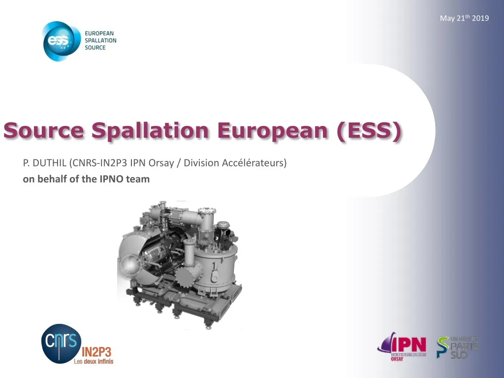
May 21 th 2019. Source Spallation European (ESS). P. DUTHIL (CNRS-IN2P3 IPN Orsay / Division Accélérateurs ) o n behalf of the IPNO team. SRF Spoke cavity β = 0.5 1/14. Cavity and liquid helium tank: construction. ( from P. DUCHESNE). Cavity: Niobium 4 mm. Tank: Titanium 4 mm.

E N D
May 21th 2019 Source Spallation European (ESS) P. DUTHIL (CNRS-IN2P3 IPN Orsay / Division Accélérateurs) on behalf of the IPNO team
SRF Spoke cavity β= 0.5 1/14 • Cavity and liquid helium tank: construction (from P. DUCHESNE) Cavity: Niobium 4 mm Tank: Titanium 4 mm Cold tuning system side Dish end: Titanium 3 mm Disk: Titanium 4 mm Reinforcement ring: Niobium 4 mm Coupler port : Titanium 3 mm Reinforcement disk: Niobium 4 mm LHe volume in the tank: 43 L Reinforcement ring: Niobium 4 mm
SRF Spoke cavity β = 0.5 2/14 • Cavity and liquid helium tank: construction Considered thickness affected to the shell for static analysis: Connection of the reinforcement rings onto the shell cavity and shell LHe tank: 4mm 2 cases were considered: - 100% of the circumference is welded - 50% of the circumference is welded 50mm (from P. DUCHESNE) 80mm 8 weld /per circle
SRF Spoke cavity β = 0.5 3/14 • Operating SRF Spoke cavities (nominal operations) 150 mm 609 mm • Bi-phase pipe: liquid/vapour interface Mean dynamic heat load for one cavity: 2.5 W 488 mm VAPEUR Bi-phase pipe Top of the cavity • Subcooledliquid Bottom of the cavity Thermal Margin Point SUPERFLUID LIQUID (He II) Ligne Bath pressure
SRF Spoke cavity β = 0.5 4/14 • Pressure Equipment Directive (PED) {Cavity + LHe tank} = cryogenic pressure vessel PS = MAWP = 1.04 barg =2.04 bara 48 Volume of the cavity helium tank at the time of definition of the cavity (proto) : 48 L (series cavity: 43 L 1.16 barg) ESSgoal: to remain in 4.3 category
SRF Spoke cavity β = 0.5 5/14 • Allowable stress criteria • Material: niobium • For niobium (and titanium), we consider an approach similar to the one of the EN 13458 for the austenitic stainless steel with A > 35%: • for normal operatingload cases (EN 13458-3): • for exceptional operating load cases (as the pressure test) (EN 13458-3): • Spoke cavities are heattreated at 600°C; for niobium: • - at 300 K, we consider: (Nb)~70 MPa; 150 MPa; (A~50%); • - at 4 K: (Nb) 300 MPa; ~ 600 MPa; • at room temperature: f ~ 50 MPa and ftest~ 75 MPa; • at cold temperature: f 200 MPa and ftest 300 MPa.
SRF Spoke cavity β = 0.5 6/14 • Allowable stress criteria • Criteria for numerical analysis • For shell elements: • for areas far from the shape discontinuities: • the general primary membrane stresses:Pm≤ f (normal operation) or Pm≤ ftest (pressure test). The post-processing of the shell elements is done by considering the neutral fiber. • for areas near the shape discontinuities: • the local primary membrane stresses:Pl≤ 1.5f (normal operation) or Pl≤ 1.5ftest (pressure test). The post-processing of the shell elements is done by considering the neutral fiber. • In all cases: • the sum primary membrane + bending stresses:Pl+Pb≤ 1.5f (normal operation) or Pl+Pb≤ 1.5ftest (pressure test). The post-processing of the shell elements is done by considering the top or bottom fiber. • at room temperature: 1,5f ~ 75 MPa and 1,5ftest~ 107,5 MPa; • at cold temperature: 1,5f 400 MPa and 1,5ftest 450 MPa.
SRF Spoke cavity β = 0.5 6/14 • Allowable stress criteria • Criteria for numerical analysis • For solid elements: as long as the maximum stress intensity is less than f (or ftest), the post-processing of stress intensity (Tresca stress) is sufficient. If not, it’s necessary to linearize the maximum stress intensity along the thickness of the elements to obtain the different primary stresses: membrane stresses, bending stresses, and membrane+bending.
SRF Spoke cavity β = 0.5 7/14 • {Cavity + LHe tank}: mechanical considerations • Linear static analysis 1: • vacuum in the cavity • pressure in LHe tank • vacuum in the vacuum vessel of the SPK CM x 1 bara • 100% of the circumferenceiswelded • 50% of the circumferenceiswelded VV stress (P. DUCHESNE) (P. DUCHESNE) • max stress at a cavity/ HPR port junction (shape discontinuity): σmax = 20 Mpa • max stress at the welded junction of a reinforcement ring/cavity junction (shape discontinuity): σmax = 30 MPa • for the rest of the cavity: stress 18 MPa
SRF Spoke cavity β = 0.5 8/14 • {Cavity + LHe tank}: mechanical considerations • Linear static analysis 1: • We can offset this result (linear analysis) • We can scale the result (linear analysis) • We can scale and offset the result (linear analysis) • 20 ≤ σmax ≤ 30 MPa • (at room T°) 2.04 = PS 1 1 =2 ~ PS 1 x1bara + 1bara= 1 0 0 0 0 3 1 0 0 1 0 0 1 e.g. MAWP at room or cold T° x2.04bara = • 40,8 ≤ σmax ≤ 61,2 MPa (at room T°) • (at cold T°: P ≤ 4.9 ≤ 7.3 bara for σmax ≤ 300 MPa) e.g. 3 bara ~ (PS+1)x1.43 for the pressure test of a cryogenic vessel (EN 13458) x2bara + 1bara = • 40,0 ≤ σmax ≤ 60,0 MPa (at room T°)
SRF Spoke cavity β = 0.5 9/14 • {Cavity + LHe tank}: mechanical considerations • Linear buckling analysis 1 of the cavity: • Based on deformed shape resulting from static analysis 1 (previous slide) 1 0 0 (P. DUCHESNE) • for the cavity: Pcrit = 30.4 bara(no safety factor) • (welds have nearly no influence)
SRF Spoke cavity β = 0.5 10/14 • {Cavity + LHe tank}: mechanical considerations • Linear static analysis 2: • vacuum in the cavity • pressure in LHe tank • pressure in the vacuum vessel of the SPK CM x 1bara • 100% of the circumferenceiswelded • 50% of the circumferenceiswelded (P. DUCHESNE) (P. DUCHESNE) • max stress at the welded junction of a reinforcement ring/cavity junction (shape discontinuity): σmax = 63 MPa • max stress at the welded junction of a reinforcement ring/cavity junction (shape discontinuity)σmax = 42 Mpa • for the rest of the cavity: stress 22MPa
SRF Spoke cavity β = 0.5 11/14 • {Cavity + LHe tank}: mechanical considerations • Linear static analysis 2: • vacuum in the cavity • pressure in LHe tank • pressure in the vacuum vessel of the SPK CM e.g. leak test of the LHe tank • If we scalethis result (linear analysis) x 1bara 1.5 1 1.5 1 0 0 e.g. Discharge of helium in the vacuum vessel (=leak) at cool-down x1,5bara = 63MPa ≤σmax≤94.5 MPa at geometric discontinuity but σ≤22 Mpafor the rest of the cavity
SRF Spoke cavity β = 0.5 12/14 • {Cavity + LHe tank}: mechanical considerations • Linear buckling analysis 2 of the cavity: • Based on deformed shape resulting from static analysis 2 (previous slides) 1 1 0 (P. DUCHESNE) • for the cavity: Pcrit = 30.0 bara(no safety factor)
SRF Spoke cavity β = 0.5 14/14 • To sum-up: • Maximum allowable pressure PS = 2.04 bara • to comply with article 4.3 of the PED • Mechanical behaviour wrt to PS (MAWP): • some margin at room T° before plastic deformation of a cavity (max stress at a shape discontinuity) • much more margin at cold T° before plastic deformation • sufficient margin wrt buckling • Operating constrains: • opening pressure of the safety device(s) below PS ~ 1 barg • pressure required by the cryogenic plant is 1.43 bara, the pressure margin between the operating pressure and safety device(s) pressure set is low. • Cavity safety strategy (ESS): • Level 1: Burst disk(s) designed for accidental scenarios = safety device • Level 2: Safety valve designed for abnormal operations and to avoid the bursting of the disk(s) • Level 3: Control valve (CV90) is designed to limit the pressure at a level lower than the opening pressure of the safety valve and is regulated at an absolute pressure
Cold helium circuits: safety devices 1/12 • Pressure scale 1 Absolute pressure (bara) Gauge pressure (barg) 2.14 1,1 x PS = Max. pressure = 1.04 2.04 PS = MAWP = 1.04 Bursting range of the burst disks Relief pressure = 1 atm 0.99 0,05: bursting pressure 1.94 0.94 Pressure margin 0.2 0.74: max. pressure for a 100% opening of the relief valve (1,05 x 0.67 0.74 bar) 1.74 0.67 (1.05 x Pset) Relief pressure (SF relief line) = 1 atm Opening area of the relief valves 0.64 5%: set pressure of the safety valve (Pset 5%) 0.61 (0.95 x Pset) 0.55: minimum pressure to allow the closing of the relief valve (0.9 x 0.61 0.55 bar) 1.55 ~0.5: PLC control valve (regulated via absolute pressure measurement) 1.5 1.43 Minimum operation pressure of the cryoplant (max. operation of the cryomodule) Is there some margin here? Operating pressure area 30·10-3 Pressure operation at 2 K
Cold helium circuits: safety devices 2/12 • Pressure scale 2 Absolute pressure (bara) Gauge pressure =P - Patm (barg) 2.14 1,1 x PS = Max. pressure = 1.04 2.04 PS = MAWP = 1.04 Bursting range of the burst disks Relief pressure = 1 atm 0.99 0,05: bursting pressure 1.94 0.94 Pressure margin 0.1 0.84: max. pressure for a 100% opening of the relief valve 1.84 Relief pressure (SF relief line) = 1.1 bara Opening area of the relief valves 0.74 5%: set pressure of the safety valve (Pset 5%) 0.65: minimum pressure to allow the closing of the relief valve 1.65 1.5 ~0.5: PLC control valve (regulated via absolute pressure measurement) 1.43 Minimum operation pressure of the cryoplant (max. operation of the cryomodule) Is there some margin here? Operating pressure area 30·10-3 Pressure operation at 2 K
Cold helium circuits: safety devices 3/12 • Burst disk sizing • Considered worst scenario: loss of beam vacuum • air leak through the power coupler window (I.D .= 100 mm) • air fully condensates onto the non insulated walls of the cavities • considered heat power density : 38 kW/m² [Lehmann, 1978 + CERN] (not widely accepted ; but very conservative !) • for 2 cavities (~2 m² each): 152 kW vaporizing saturated He II • Helium properties: • Disk sizing (ISO 21013,EN 13648-3): • Mass flow rate: • Subsonic flow considered as • Min. relief cross section: • at max discharge pressure • to minimize Lv • to maximizes (vapour) mass flow rate • Burst pressure: • 1.94 to 2.04 bara • (vaporization of saturated He II) Min. burst disk I.D.
Cold helium circuits: safety devices 4/12 • Burst disk(s) location(s) 1x Burst disk90 mm 2x Burst disks100 mm Prototype SPK CM Series SPK CM
Cold helium circuits: safety devices 5/12 • Burst disk technology • Prototype SPK CM • Series SPK CMs New design by Witzenmann: circular knife to obtain a better cutting of the disk and a larger flow area Prototype: CF flange Series: welded interface Dimensions updated by Witzenmann on 2016/04/07 Ø97mm Ø90mm
Cold helium circuits: safety devices 6/12 • Burst disk: pressure drop in the exhaust line • Helium properties: • Burst pressure: 1.94 to 2.04 bara • Mass flow rate is evaluated at max. discharge pressure: 2.04 bara (cf. burst disk sizing) ~4 kg/s per cavity (~8 kg/s total) • Pressure drops are evaluated by considering a discharge pressure of 1.94 at the inlet of the burst disk to maximize the pressure drops (lowering the density) • He saturated vapour is considered (not liquid nor diphasic flow) to maximize the pressure drops • He properties (density and viscosity) are pressure dependant • Estimated total volume of LHe in the circuit: ~ 120 L
Cold helium circuits: safety devices 7/12 • Burst disk: pressure drop in the exhaust line • EN 13648-3 • ΔP in the exhaust line shallbe 3% x burst pressure Δpmax 30 mbar ! Exhaust line = from the outer jacket of the cryogenicreservoir to the outlet • Allowedoverpressureduring accident: 110 % x Ps pmax = 2144 mbara int = 63 mm LHe tank outer jacket Singular pressure drop due to the fluidentering the exhaust line not to takeintoaccount? Not clear in EN13648 nor in ISO 21013 Weconsiderthose pressure drops (~90mbar) 4 kg/s 4 kg/s • Weconsider all: • - regular pressure drops (friction) • - Singular pressure drops in: • . cavitiesoutlets (intrances of exhaust line) • . tee junctions and cones Equivalent network Δpmax ~ 160 mbar > 30 mbara pmax = 2085 mbara< 2144 mbara In agreement with EN13648 (NB: if discharge pressure = 2.04 bara,pmax= 2168 mbara> 2144 mbara
Cold helium circuits: safety devices 8/12 • Burst disk: pressure drop in the exhaust line • It is not possible to respect Δpmax 30 mbar in the burstdiskexhaust line withsuch Ps considering pressure drops at the entrance of the cavity. • However: • we are talking about tens of mbar • wedon’tforeseeanymechanicalrisk for the Spoke cavities (and not for people). .
Cold helium circuits: safety devices 9/12 • PID of the cold helium circuits Safety device Cryogenic control valve
Cold helium circuits: safety devices 10/12 • Cryogenic Valves
Cold helium circuits: safety devices 11/12 • Burst disk Safety valves protection • Considered worst scenario: • HP He supply: 3 bara, 5 K • Valves CV01, CV02and CV03 fully opened (at kv max) • Cool-down phase (He return line is warm) • VLP valve CV04 closed max. mass flow rate 3 bara, 5 K CV03 (shut-off) Kv=1.82 m3/h 106.8 g/s 2.7 bara, 5 K CV02 (SRF cool-down) Kv=1,014 m3/h 97,2 g/s CV01 (JT) Kv=0,1 m3/h 9.6 g/s 1.74 bara 300 K CV90 Kv=10.9 m3/h 34.0 g/s SV90 72.8 g/s 1.1 bara
Cold helium circuits: safety devices 12/12 • Protection of the burst disk SV90: procurementisongoing SVs: 2x Circle seal1/2" opening at 140 – 150 mbar CV90: VELAN DN20 KV = 14.7m3/h Prototype SPK CM Series SPK CM
CSP12 28 Novembre 2014 Thank you for your attention