Download
1 / 24
240 likes | 601 Views
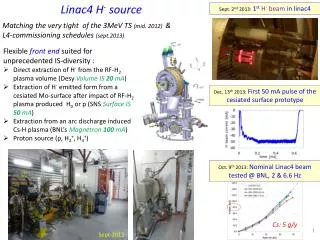
H - Ion Source Development. Dan Faircloth. ISIS Operational Ion Source. Penning H - ion source Surface Plasma Source (SPS) 35 mA through 0.6 10 mm aperture 200-250 s, 50 Hz 1% duty cycle 20 ml/min H 2 3 g/month Cs 0.17 mm mrad (665 keV, 35 mA, rms)

E N D
H- Ion Source Development Dan Faircloth
ISIS Operational Ion Source Penning H- ion source Surface Plasma Source (SPS) 35 mA through 0.610 mm aperture 200-250 s, 50 Hz 1% duty cycle 20 ml/min H2 3 g/month Cs • 0.17 mm mrad (665 keV, 35 mA, rms) 20-30 day average lifetime
H- Ion Beam Extract Electrode Penning Pole Pieces Discharge Region Aperture Plate Ceramic Anode Source Body Copper Spacer Cathode Mica 10mm Mounting Flange
Platform DC Power Supply Platform Ground 35kV Pulsed Extract Power Supply 17kV - + Laboratory Ground 18kV Extraction Electrode, Coldbox and Analysing Magnet all Pulsed - + 35keV H- Beam 53.7mm Post Extraction Acceleration Gap
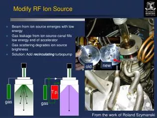
Increase Pulse Length Increase Output Current Reduce Emittance Maximise Lifetime Development Goals 200µs to 1.5ms 35mA to 70mA
Steady State Solution 600 520 440 360 280 200 Cathode Surface ΔT= 73 ºC Computational Fluid Dynamic Cooling Calculation ΔT= 39 ºC Anode Surface Transient Solution 1000μs duty Thermal Modelling 3D Finite Element Model of the Ion Source using ALGOR.
3D Finite Element Model of the Ion Source using MAFIA. Terminated Pierce Extract Existing Extract Potential in Extract Region 17 keV normalised Hrms= 0.04 mm mrad Vrms= 0.16 mm mrad 17 keV normalised Hrms= 0.03 mm mrad Vrms= 0.03 mm mrad Magnetic Field in Coldbox Correctly Terminated Analysing Field 0T 0.5T Electromagnetic Modelling
Ion Source Assembly Pole tip extensions on the 90° Analysing Magnet Penning Field B Magnet Assembly ISDR Infrastructure Changes Top Loading Ion Source Separate Penning Field
Penning Field B ISDR Infrastructure Changes Top Loading Ion Source Separate Penning Field Ion Source Assembly Magnet Assembly
Collaboration with IHEP, CAS Dr. Ouyang and Prof. Zhang Feb 2007: Dr. He Wei testing ion source components manufactured in China.
Increase Pulse Length Increase Output Current Reduce Emittance Maximise Lifetime 200µs to 1.5ms 35mA to 70mA Development Goals
σ = 17.6 eV +/- 1.5 eV Transmission (%) δ(Transmission) / δ(−Vb) (%/V) Bias Voltage (V) Bias Voltage (V) Discharge Current (A) Transmission (%) Spectrum width σ (eV) Faraday Cup H- Beam I Potential Hill Discharge Current (A) Bias Voltage (V) Retarding Potential Energy Analyzer Work done in collaboration with Oxford University
100 x ‘(mRads) 50 0 -50 -100 -60 -30 0 30 -60 x (mm) 17 kV Extract Potential 62 mA Beam Current 100 50 y ‘(mRads) 0 -50 -100 -60 -30 0 30 -60 y (mm) 0.84 norm πmm mRad 0.92 norm πmm mRad
10 kV Extract Potential 32 mA Beam Current 100 100 50 50 x ‘(mRads) y ‘(mRads) 0 0 -50 -50 -100 -100 -60 -60 -30 0 30 -60 -30 0 30 -60 x (mm) y (mm) 0.48 norm πmm mRad 0.55 norm πmm mRad
6.5 kV Extract Potential 13 mA Beam Current 100 100 50 50 x ‘(mRads) 0 0 y ‘(mRads) -50 -50 -100 -100 -60 -60 -30 0 30 -60 -30 0 30 -60 y (mm) x (mm) 0.16 norm πmm mRad 0.32 norm πmm mRad
Scintillator Measurements 5 kV Ext 5.5 kV Ext 6 kV Ext 6.5 kV Ext 7 kV Ext 8 kV Ext 9 kV Ext 11 kV Ext
Pepper Pot Emittance Measurement • To help understand why the emittance is so large • To allow optimised design of the LEBT for the Front End Test Stand • To develop diagnostic experience for the FETS collaboration Mounting flange Details in the next talk Window Support rods Moving rod Scintillator and Pepperpot Camera
Scanning Pepperpot and Scintillator studies Space charge studies with Krypton Different extraction geometries Different post acceleration gap Plasma meniscus modelling More detailed beam transport modelling Different materials for extended lifetime studies Future Work