Download

1 / 27
270 likes | 555 Views
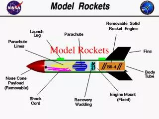
Characterization of Model Rockets in Flight. Section 4, Team 1 Student 1, Student 2, Student 3 and Student 4 . Introduction. Using prototypes can prevent costly errors in complicated systems Different types of sensors are required to collect a wide variety of data

E N D
Characterization of Model Rockets in Flight Section 4, Team 1 Student 1, Student 2, Student 3 and Student 4
Introduction • Using prototypes can prevent costly errors in complicated systems • Different types of sensors are required to collect a wide variety of data • The current set of rockets follow in the footsteps of Mudd I and Mudd II
Preparation: Rocket Launch • Following a series of checklists: • Configure R-DAS and Video • Load parachute and ejection charge • Install motor • Followed NAR and Tripoli guidelines http://mpcardenas.smugmug.com/gallery/4805272_ZJqsr#285517109_ANAvP
Procedures: Data Collection • R-DAS - Rocket Data Acquisition System • Three batches of sensors: • IMU • Strain Gauges • Thermistor and Pressure Transducers • These batches are used to model: • Velocity and position • Vibration and response • Atmospheric variables • Calibration curves are used to convert from digital signals to physical variables • Video camera © Bruce Yan
Theory: Rocket Flight Simulation • The MATLAB script numerically integrates acceleration given by an experimental thrust curve • It makes several simplifying assumptions: • The rocket only moves in two dimensions • The wind exerts a constant lift force • The rocket travels straight for 6 feet along the rail. Then it instantaneously changes direction towards the wind • The coefficient of drag is .75
Theory: IMU • The IMU contains: • Accelerometers • Gyroscopes • Sensors are mutually orthogonal to create a local set of axes • Can convert between local axes to global variables by using a rotational matrix • Data were used to recreate the rocket flight path • The global variables can be found from the local variables by using a rotation matrix.
Theory: IMU IMU Calibration Curve
Medium Rocket: IMU • A variety of engines were used • Theoretical models were created using MATLAB and RocSim • Flights were modeled using the IMU data in conjunction with a MATLAB script • Both the theoretical models overestimated the altitude of the apogee
Rocket Flight Model:Medium IMU Experimental Modeling of IMU Rocket Flight 2 (Motor G79W, 4/26/2008)
Rocket Flight Model:Medium IMU Experimental 3D Modeling of IMU Rocket Flight 2 (Motor G79W, 4/26/2008)
Rocket Flight Video:Medium IMU © Masanori Honda
Small Rocket: IMU • Tragedy Strikes! • The R-DAS did not detect apogee and deploy the parachute • Data was irrevocably damaged by the fall © Masanori Honda
2 3 4 1 Theory: Thermistors • The locations of the Thermistors are shown below • Temperature can be found as a function of the resistance of the thermistor using the Steinhart – Hart (S-H) Equation displayed below.
Theory: Pressure Sensors • The rocket has two pressure sensors • R-DAS • IMU • The two pressure sensors were calibrated with an desiccation chamber • The altitude of the rocket can be calculated using the relationship between altitude and the atmospheric pressure shown below.
2 3 4 1 Medium Rocket: Temperature and Pressure • Apogee • R-DAS: 199.8 m • IMU: 199.7 m Medium Temperature and Pressure Flight 1(Motor G67R, 4/19/2008)
Theory: Vibration • The Modal shape of a linear objects can be given by the following equation • The first three Modal shapes should have the shapes below • The following diagram displays the location of the strain gauges on the rocket
Medium Rocket: Vibration Plot of time vs raw data for 3-4 seconds Plot of time vs raw data for 4-4.5 seconds
Medium Rocket: Vibration Plots of sensor positions to corrected magnitude
Conclusions • The IMU rocket showed: • Theoretical models consistently overestimate the actual apogee by 30-40% • The temperature pressure rocket: • Consistency between two pressure sensors • Temperature of the rocket during flight • The vibrational rocket: • Only the first mode was observed • The first resonance occurred at 43 Hz © Masanori Honda
Further Work • Suggestions for design improvement: • Change from the R-DAS to another type of data acquisition system due to issues: • The R-DAS altitude sensor does not reliably detect apogee due to low resolution • The R-DAS doesn’t sample at high enough of a frequency to detect higher vibration modes • Further rocket flights to determine any inefficiencies in the rocket design © Masanori Honda
Acknowledgements • Professor Spjut • Professor Cardenas • Professor Miraghaie • Professor Yang • Professor Wang • Proctor 1 • Proctor 2
Acknowledgements • And the E80 students who have risked their lives for the course © Med Temp. Press. Rocket
Questions? ???