Download

1 / 17
170 likes | 311 Views
Arson Robot. Matt Boyden, Tim Crowley, Andrew Hollyer. PROBLEM STATEMENT. Design and build a robot to assist in State Police arson investigations. The robot must be able to: navigate inside a burned building carry and protect a hydrocarbon sensor take samples of charred material.

E N D
Arson Robot Matt Boyden, Tim Crowley, Andrew Hollyer
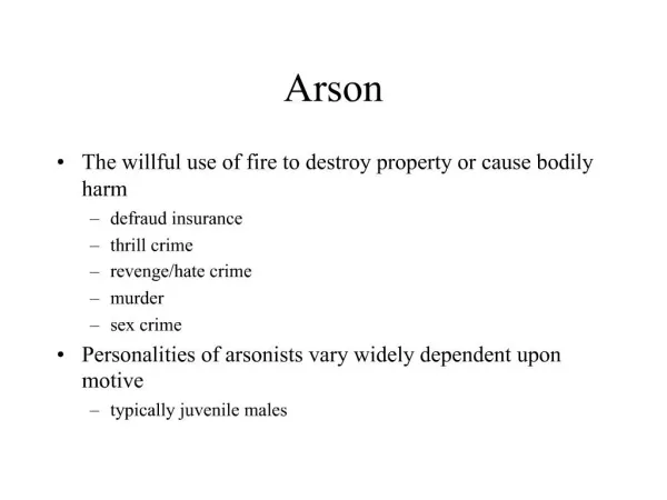
PROBLEM STATEMENT Design and build a robot to assist in State Police arson investigations. The robot must be able to: • navigate inside a burned building • carry and protect a hydrocarbon sensor • take samples of charred material
CURRENTLY AVAILABLE MANY VEHICLES ARE AVAILABLE MOST DO NOT PROVIDE ROOM FOR ADAPTION OF THE HYDROCARBON SENSOR VEHICLES ARE HIGH PRICED
KEY SPECIFICATIONS • Can travel over debris at an incline of up to 30° • Can travel under debris that is no less than 1½ ft above the driving surface • Can take samples of charred debris ranging in size from ash to small fragments of wood with a max weight of 2 lbs • Carries and protects hydrocarbon sensor • Controllable from a distance of up to 50 ft • Sample collector can be decontaminated • Under two feet wide • Light weight (under 60 lbs)
POSSIBLE SOLUTIONS • TRACKED VEHICLE WITH UMBILICAL CONTROLS AND POWER AND A BUCKET FOR SAMPLING • LARGE TIRED VEHICLE WITH ONBOARD BATTERY POWER AND A GRAPPLE FOR SAMPLING
ORDER OF OPERATIONS • BUILD A VEHICLE CAPAPLE OF MEETING THE SPECIFICATIONS • PROVIDE A MOUNT FOR THE HYDROCARBON SENSOR AND PROVIDE AN AUDIO FEED TO THE OPERATOR • ENABLE THE VEHICLE TO TAKE SAMPLES
EXPERIMENTS & CALCULATIONS Coefficient of friction (μ) = .8 Approximate Weight (w) = 56 lbs Hub Circumference (C) = 3π in. Hub Radius (r) = 1.5 in. Desired Maximum speed (V) = 84 ft./min. Gearing Ratio (VR) = 3:1 Axle Diameter σ = MC/I = 1210 psi use Dia = 3/8 in Force (F) required to move robot = μw = (.8)(56 lbs) = 44.8 lbs Torque (τ) required to move robot = Fr = (44.8 lbs)(1.5 in.) = 67.2 in·lbs Rotational speed (ω1) at outside of hubs = CV = (3πin.)(84 ft./min.) = 107 rad./min. Rotation speed (ω2) at motor = (ω1)/(VR) = 4.908 rad/min Rotation speed (n) at motor in rpm = (ω2)(180/π) = 281.25 rpm Power (P) = (τ)(n)/63,000 = (67.2 in·lbs)(281.25 rpm)/63,000 = .3 hp
RESEARCH & DESIGN RESEARCH DONE ON TRACK SYSTEMS SHOWED THIS SYSTEM AS A POSSIBLE SOLUTION. 3 1 2 4
PARTS DESIGNED FOR THE TRACKS HUBS FOR THE TRACK • MODELED IN INVENTOR • TURNED ON LATHE AND KNURLED FOR FRICTION • FOUR DRIVE HUBS, FOUR IDLERS
BUILDING THE VEHICLE MOTORS DONATED • 12 VOLT • 6 RPM • 900:1 GEARBOX • 90 in-lb TORQUE • 2 AMPS
BATTERY BATTERY + + - - WIRING OVERVIEW MOTOR MOTOR FUSE SWITCH SWITCH
NEXT GENERATION • POSITIVE DRIVE TRACK SYSTEM • LARGER DRIVE SHAFTS • EASIER ALIGNMENT OF TRACKS • LIGHTER AND BETTER BALANCED FRAME
THANKS TO: • PROFESSOR SAM COLWELL • ROV TECHNOLOGIES inc. • OESCO inc • Dr. DAWN CARLETON • PROFESSOR PAUL JOHNSON • PROFESSOR MARY WALDO