Download

1 / 16
160 likes | 206 Views
Learn to calculate cross-sectional area, determine strengths, and analyze safety factors for truss members. Understand the impact of forces, materials, and design on structural integrity.

E N D
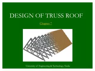
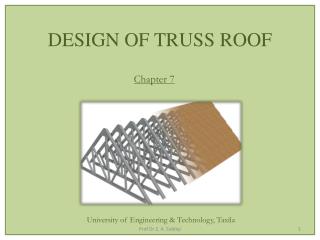
Truss Factor of Safetyand Characterization • Factor of Safety • Member Cross-Sections • Effecting Tensile and Compressive Strengths • Characterizing Truss Members
Learning Objectives • Calculate cross sectional area of a truss member • Explain factors that affect the tensile and compressive strength of a truss member • Explain the principle of the lever tool • Experimentally determine the tensile and compressive strengths of truss members • Graph and analyze the experimental data • Calculate Factor of Safety for every truss member
Factor of Safety • Design uncertainty • Excessive loads: vehicles exceeding specifications, wind, snow, earthquakes, etc • Construction: material variances, workmanship, etc • Design Models: accuracy of design simulations
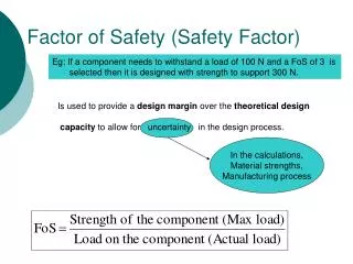
Failure Level Actual Level Factor of Safety • Designers make a bridge stronger than design target • Factor of Safety = • Most codes require minimum Factor of Safety > 1.6
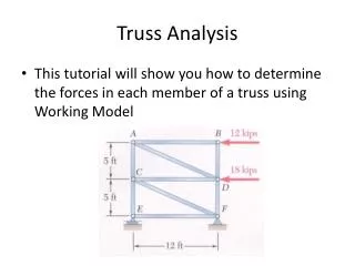
Failure Level Actual Level Truss Characterization and Factor of Safety • Factor of Safety = • Actual level is calculated by Method of Joints • Need characterization data of the failure level for a truss member
Tensile Strength Characteristics • depends on the cross-sectional area • depends on the material • does not depend on the length • does not depend on the cross-sectional shape
Compressive Strength Characteristics • depends on the cross-sectional area • depends on the material • depends on the length • depends on the cross-sectional shape
Summary of Material Effects on Tensile and Compressive Strengths
F1 F2 L1 L2 Lever Concept Lever Relationship: F1 * L1 = F2 * L2
Testing Machine This tester works on the lever principle
Tensile Strength Characterization • Make test specimens, see Learning Activity #2 • Clamp specimen to T-Line • Conduct tension tests
Tensile Strength • Plot Tensile Strength (Newtons) vs. Member Width (mm) • Generate linear regression through (0,0)
Compression Strength Characterization • Make test specimens, see Learning Activity #2 • Support specimen on felt pads at C-Line • Conduct compression tests
Compressive Strength • Plot Compressive Strength (Newtons) vs. Member Length (cm) • Generate best fit curve to data
Acknowledgements • This presentation is based on Learning Activity #2, Test the Strength of Structural Members from the book by Colonel Stephen J. Ressler, P.E., Ph.D., Designing and Building File-Folder Bridges