Download

1 / 66
710 likes | 961 Views
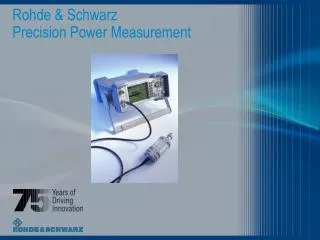
Precision Power Measurement Solutions from Bird. Agenda. National Standards Traceability- Challenges & Bird’s Solution RF Metrology Paths at Bird Electronic Corporation High power RF Calorimetry Low power microwave attenuation Low power microwave power MCS (master calibration system)

E N D
Precision Power Measurement Solutions from Bird
Agenda • National Standards Traceability- Challenges & Bird’s Solution • RF Metrology Paths at Bird Electronic Corporation • High power RF Calorimetry • Low power microwave attenuation • Low power microwave power • MCS (master calibration system) • Test Setups & system considerations • 4020 Series Power Sensors and the 4421 Power Meter • Typical Field Power Measurement Systems
National Standards Traceability- Challenges & Bird’s Solution
National Reference Standard NIST Measurement Reference Standard Bird Metrology Working Standard Bird Manufacturing Facility Power Sensors Generic Traceability Path
Power Measurement Requirements of the Semiconductor Industry Various frequency & power combos 40 kW Power 13.56 Mhz Frequency
Accuracy Capability of the Scientific Community Bird’s performance range & capability Power NIST, NPL etc. Frequency
Accuracy Capability of the Scientific Community Bird’s performance range & capability Calorimetry Path Precision Attn & Power Path Power NIST, NPL etc. Frequency
Bird’s Multi-Path Solution High Power RF Calorimetric Path NIST AC & DC Standard Low Power Precision Attenuator RF & Microwave Path Low Power RF & Microwave Power Path NIST Attenation Standard NIST Standard Micro- Calorimeter < 10 mw < 10 mw Primary Lab AC Voltage & Current Stds. NIST Fixed Attenuator Set Primary Standard Thermistor CN Mount Working Standard Precision 60 Hz Power Analyzer Working Standard Working Standard VNA Thermistor Mount Measurement Ref. Standard High Power Calorimeter Coupler Verification Cal Factor Verification MCS Transfer Standard MCS Transfer Standard Couplers + Power Meter Test Setups Test Setups 4027, 4028 4027, 4028 4024, 4025 4024, 4025 Model 43 Model 43
Calibration Subtleties of the Bird System • +/- 1% calibration requirements dictate daily calibration • +/- 3% is calibrated every 6 months • +/- 5% is calibrated annually • Cross correlations are on-going and constant • Multiple paths are used to cross correlate high power & high frequency standards • It is capital intensive, time consuming, and demands high skill levels, but worth every effort in order to guarantee the high accuracy demands of the semiconductor industry
RF Metrology Paths at Bird Electronic Corporation • High power RF Calorimetry • Low power microwave attenuation • Low power microwave power • MCS (master calibration system) • Test Setups & system considerations
High Power RF Calorimetric Path NIST AC & DC Standard • Calorimetry is the critical link • between high power AC standards • & high power RF standards Primary Lab AC voltage & Current Stds. Working Standard Precision 60 Hz Power Analyzer Measurement Ref. Standard High Power Calorimeter
Calorimetric Power Meters 6091 Power (kW) = .263 x flow rate (GPM) x T (0C) 8860
Calorimeter Block Diagram Bird Metrology Manufacturing Facility
Characteristics of Calorimetric Power Meters • Highly Accurate, Especially When Using 60Hz Substitution Technique • Measures True Heating Power, Regardless of Harmonic Content or Modulation Characteristics of Signals • Requires Careful Setup and Maintenance, Due to Coolant Characteristics • Long Settling Time
AC Substitution Method 60 Hz AC Source Precision AC PowerMeter RF Calorimeter RF Source • Measure 60 Hz power into calorimeter w/AC Power meter • Adjust calorimeter display to match AC power meter • Accuracy of AC standard has now been transferred to calorimeter • When RF is supplied to load, read calibrated watts from calorimeter display
AC Substitution Technique • Use Low Distortion 60Hz Source • Calibrate Calorimeter Using Precision 60Hz Power Meter (Accuracy = <0.1%) • Apply Unknown RF Source to Calorimeter • Adjust Coolant Flow Rate to Maintain ΔT Across Load of > 2º C • Allow 1 hour For Stabilization
Transfer of Accuracy from AC to RF VSWR AC (60 Hz) RF frequency • Calorimetric load has virtually identical response at both AC & RF
Calorimetric Stability Error Days
Low Power Precision AttenuatorRF & Microwave Path NIST Attenuation Standard < 10 mw • Provides the important link • between low power, high frequency • attenuation values & high frequency • coupling values NIST Fixed Attenuator Set Working Standard VNA Coupler verification MCS Transfer Standard MCS Transfer Standard
VNA Working Standard • Transfers the accuracy of the VNA to the precision coupler when the coupling value is determined Precision Coupler
VNA Attenuation Standards • Attenuation kit traceable to NIST Attenuation Kit
Low PowerRF & Microwave Power Path NIST Standard Micro- Calorimeter < 10 mw Provides the link between high frequency low power standards and high frequency power meters Primary Standard Thermistor CN Mount Working Standard Thermistor Mount MCS Transfer Standard MCS Transfer Standard Cal Factor verification
Working Standard Thermal Power Meter CN Thermister Mount • Cal factor of power meter is verified with reference to Thermister mount
MCS Transfer Standard Provides the combinational accuracy of calibrated high frequency power & coupling standards into a single calibrated device that can be used as a measurement standard in a high frequency, high power test setup MCS Transfer Standard MCS Transfer Standard
Characteristics of Directional Coupler-Thermal Power Meter Standards • Wide Dynamic Range • Useful Frequency Range Determined by Directional Coupler • Complicated Error Budget • Internal Reference Uncertainty • Mismatch Uncertainty • Calibration Factor Uncertainty • Fundamental Accuracy Limited by Knowledge of Directional Coupler Attenuation, as well as Power Meter Error Sources. • Mismatch Uncertainty is a Major Contributor to Total Uncertainty
Precision Power Measurement Test Setups Test Setups Test Setups 4027, 4028 4027, 4028 Model 43 Model 43 4024, 4025
4027A +/-1% Calibration System These two measurements must agree within +/- .2%
A Typical Field Calibration Setup Bird 4020AM Power Sensor p2 p1 p2 RF Matching Network p2 p1 p1 Bird Oil load 5 kW RF Generator at 13.56 MHz p2 Plasma Etching Chamber Bird 4421 Power Meter Mismatches are present at each interconnection of system components
Mismatch Uncertainty p2p1p2S p1p2S p1 p2 S p2S Total reflected signal p2 +/- p1p2p2 = p2’
Mismatch Uncertainty 1 + p2’ VSWR (apparent) = p2 +/- p1p2p2 = p2’ 1 – p2’ 1 + ( p2 +/- p1p2p2 ) 1 + p2 +/- p1p2p2 VSWR (apparent) = = 1 - ( p2 +/- p1p2p2 ) 1 - p2 -/+ p1p2p2 Recognize that this expression can be approximated as the product of Very small contribution 1 + p2 1 +/- p1p2p2 1 +/- p1p2p2 + p2 +/- p1 p32 x = 1 – p2 1 -/+ p1p2p2 1 -/+ p1p2p2 + p2 +/- p1 p32 Then: 1 +/- p1p2p2 VSWR (apparent) VSWR (true) x ~ 1 -/+ p1p2p2
1 - p1p2p2 Lower limit of multiplier factor = = F- 1 + p1p2p2 1 + p2 Lower uncertainty limit of measured VSWR = F- 1 – p2 1 + p1p2p2 Upper limit of multiplier factor = = F+ 1 - p1p2p2 1 + p2 Upper uncertainty limit of measured VSWR = F+ 1 – p2 Mismatch Uncertainty 1 +/- p1p2p2 VSWR (apparent) VSWR (true) x ~ 1 -/+ p1p2p2 • The true VSWR is multiplied by an uncertainty factor which can only be controlled • by carefully choosing the reflection coefficients (p1 and p2) at the source and test points
Mismatch Uncertainty Mu (%) = 100 [(1 Pg Pl)2 – 1] ± Where: Pg = Reflection Coefficient of Source Pl = Reflection Coefficient of Load Pg and Pl are FREQUENCY DEPENDENT QUANTITIES!
Transmission Uncertainty p2p1p2S p1p2S p1 p2 S p2S Total transmitted signal S(1 +/- p1p2) +/- dB (ripple) = 20 log | 1- p1p2 |
Transmission Uncertainty High point Measurement uncertainty flatness Ripple averaged out Low point • If data is taken at discrete points, then each individual • reading carries an uncertainty of +/- x dB
4027A +/-1% Calibration System These two measurements must agree within +/- .2%
Effects of Harmonics on Power Measurement • 4027 Power Sensor Detector Scheme is Very Sensitive to Harmonics in the Signal. • 4027 is Calibrated with Signals Having Harmonics of Less than –60dBc. • Signals with Harmonic Content Greater Than –60dBc will Cause Offsets in Power Readings • Effects of Harmonics are Determined not Only by Diode Response, but Also by Directional Coupler Response Characteristics, as well as Phase Relationships of Harmonic.
Worst Case Errors Effects of Harmonics on Power Measurement
Effects of Modulation on Power Measurement • Detector Scheme Used in 4027 is Sensitive to Amplitude Modulation of the Signal. • Magnitude of Change in Power reading is Related to Power Level and Instrument Range. • Approximate Error: • At 10% of Full Scale: 5% AM Results in 2% Error • At 90% of Full Scale: 5% AM Results in 8% Error
Additional Tips for MakingAccurate Power Measurements • Know the effects of the mismatches present in the system architecture on the power measurement uncertainty • Avoid the use of multiple adapters or non-compensated (high VSWR) adapters between cables and components • Perform a system error budget to quantify the effects of mismatches and component tolerances in the system • Avoid the use of long interconnecting cables, as the ripple period will be more frequent as the length is increased for a given frequency • Use coupler based measurement techniques when the load is unstable or poor in performance compared to the system line impedance • Averaging techniques over wider frequency bands can be effective in minimizing the effect of mismatch uncertainties
4421/4020 Series Power Meters • Highly Accurate, Highly Repeatable Power Meter System • Long Product History, Introduced in 1988 • Has Become the Power Meter of Choice in Semiconductor Processing Applications • Extremely Wide Dynamic Range
4027A PrecisionPower Sensor Model Power Range Frequency VSWR Range Directivity Insertion Loss 4027A12M 300 mW to 1 kW 10-15 MHz 1.0 to 2.0 28 dB <0.05 dB 4027A250K 3 W to 10 kW 250-400 kHz 1.0 to 2.0 28 dB <0.05 dB 4027A400K 3 W to 10 kW 400-550 kHz 1.0 to 2.0 28 dB <0.05 dB 4027A800K 3 W to 10 kW 800-950 kHz 1.0 to 2.0 28 dB <0.05 dB 4027A2M 3 W to 10 kW 1.5-2.5 MHz 1.0 to 2.0 28 dB <0.05 dB 4027A4M 3 W to 10 kW 3-5 MHz 1.0 to 2.0 28 dB <0.05 dB 4027A10M 3 W to 10 kW 10-15 MHz 1.0 to 2.0 28 dB <0.05 dB 4027A25M 3 W to 10 kW 25-30 MHz 1.0 to 2.0 28 dB <0.05 dB 4027A35M 3W to 10 kW 35-45 MHz 1.0 to 2.0 28 dB <0.05 dB 4027A60M 3W to 6kW 45-65 MHz 1.0 to 2.0 28dB <0.05 dB • Designed for Service in Semiconductor Processing Applications • 1% Accuracy at Calibration Points • Several Models to Address Specific Semiconductor Power Levels and Frequencies ±