Download

1 / 141
1.62k likes | 2.28k Views
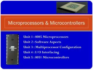
MICROCONTROLLERS & APPLICATIONS. S uresh K umar K B. Lecturer in Electronics. UNIT - II. 8051. MICROCONTROLLER ARCHITECTURE. FEATURES. 8-bit CPU optimized for control applications Extensive Boolean processing (Single-bit logic) capabilities 64K Program Memory address space

E N D
MICROCONTROLLERS & APPLICATIONS Suresh Kumar KB Lecturer in Electronics
UNIT - II 8051 MICROCONTROLLER ARCHITECTURE SKB's
FEATURES • 8-bitCPU optimized for control applications • Extensive Boolean processing (Single-bit logic) capabilities • 64K Program Memory address space • 64K Data Memory address space • 4K bytes of on-chip Program Memory • 128 bytes of on-chip Data RAM • 32 bidirectional and individually addressable 1/0 lines • Two 16-bit timer/counters • Full duplex UART • 6-source/5-vector interrupt structure with two priority levels • On-chip clock oscillator SKB's
P1 P0 RESET + _ P3 P2 XTAL PIN DETAILS SKB's
Timer 0 Timer 1 TXD RXD P0 P1 P2 P3 BLOCK DIAGRAM 4K ROM Interrupt Control 128 RAM CPU OSC Bus Control 4 I/O Ports Serial Port
ARCHITECURE All SKB's
ARCHITECURE 1 SKB's
ARCHITECURE 2 SKB's
ARCHITECURE 3 SKB's
60K 64K 64K 4K MEMORY STRUCTURE External External SFR EXT INT 128 EA = 0 EA = 1 Program Memory Data Memory SKB's
INTERNAL RAM STRUCTURE Inirect Addressing Only Direct Addressing Only SFR Direct & Indirect Addressing 128 Byte Internal RAM SKB's
128 BYTE RAM 128 BYTE INTERNAL RAM General Purpose Area BIT Addressable Area Register Banks Reg Bank 3 Reg Bank 2 Reg Bank 1 Reg Bank 0 SKB's
REGISTER BANK STRUCTURE Bank 3 Bank 2 Bank 1 Bank 0 Program Status Word - PSW SKB's
SFR SKB's
UNIT - III MICROCONTROLLER APPLICATIONS & INTERFACING SKB's
TIMERS • SERIAL PORT • INTERRUPTS SKB's
TIMERS • SERIAL PORT • INTERRUPTS SKB's
Mode 0 Mode 0 Mode 1 Mode 1 Mode 2 Mode 2 Mode 3 TIMERS Timer 0 Timer 1 SKB's
TIMER / COUNTER OSC ÷12 TF (1 Bit) TL (8 Bit) TH (8 Bit) INTERRUPT SKB's
x TIMER 0 OSC ÷12 TL0 TH0 TF0 INTERRUPT SKB's
TIMER 0 – Mode 0 13 Bit Timer / Counter X TL0 (5 Bit) TH0 (8 Bit) TF0 OSC ÷12 INTERRUPT Maximum Count = 1FFFh (1111111111111) SKB's
TIMER 0 – Mode 1 16 Bit Timer / Counter X TL0 (8 Bit) TH0 (8 Bit) TF0 OSC ÷12 INTERRUPT Maximum Count = FFFFh (1111111111111111) SKB's
TIMER 0 – Mode 2 8 Bit Timer / Counter with AUTORELOAD X TL0 (8 Bit) TF0 OSC ÷12 INTERRUPT Reload TH0 (8 Bit) Maximum Count = FFh (11111111) SKB's
TIMER 0 – Mode 3 Two - 8 Bit Timer / Counter X OSC ÷12 TL0 (8 Bit) TF0 INTERRUPT TH0 (8 Bit) TF1 OSC ÷12 INTERRUPT SKB's
TIMER 1 OSC ÷12 TF1 TL1 TH1 INTERRUPT SKB's
OSC ÷12 Y TIMER 1 TF1 TL1 TH1 INTERRUPT SKB's
TIMER 1 – Mode 0 13 Bit Timer / Counter Y TL1 (5 Bit) TH1 (8 Bit) TF1 OSC ÷12 INTERRUPT Maximum Count = 1FFFh (1111111111111) SKB's
TIMER 1 – Mode 1 16 Bit Timer / Counter Y TL1 (8 Bit) TH1 (8 Bit) TF1 OSC ÷12 INTERRUPT Maximum Count = FFFFh (1111111111111111) SKB's
TIMER 1 – Mode 2 8 Bit Timer / Counter with AUTORELOAD Y TL1 (8 Bit) TF1 OSC ÷12 INTERRUPT Reload TH1 (8 Bit) Maximum Count = FFh (11111111) SKB's
Gate TF1 C/Ť TR1 M1 TF0 M0 TR0 Gate IE1 IT1 C/Ť IE0 M1 M0 IT0 SFRs Related to TIMER TMOD Timer 1 Timer 0 TCON Timers Interrupt SKB's
TIMERS • SERIAL PORT • INTERRUPTS SKB's
Write to BUFFER RXD O/P S SBUFF Q D CL Zero Detector Start Shift TX Control CLK TX Clock TI Send Serial Port Interrupt TXD RI RX Clock Receive RX Control RI Shift Clock Start Shift REN 1 1 1 1 1 1 1 0 RXD I/P Input Shift Register Load to BUFFER SBUFF Read From BUFFER SKB's
SERIAL PORT– Mode 0 The Serial Port in Mode-0 has the following features: • Serial data enters and exits through RXD • TXD outputs the shifl clock • 8 bits are transmitted / received • The baud rate is fixed at (1/12) of the oscillator frequency SKB's
SERIAL PORT– Mode 0 SKB's
SERIAL PORT– Mode 0 SKB's
SERIAL PORT– Mode 1 • The Serial Port in Mode-1 has the following features: • • Serial data enters RXD • • Serial data exits through TXD • • On receive, the stop bit goes into RB8 in SCON • • 10 bits are transmitted / received • Start bit (0) • Data bits (8) • Stop Bit (1) • • Baud rate is determined by the Timer 1 over • flow rate. SKB's
SERIAL PORT– Mode 1 SKB's
SERIAL PORT– Mode 1 SKB's
SERIAL PORT– Mode 2 • The Serial Port in Mode-2 has the following features: • • Serial data enters RXD • • Serial data exits through TXD • • 9th data bit (TB8) can be assign value 0 or 1 • • On receive, the 9th data bit goes into RB8 in SCON • • 11 bits are transmitted / received • Start bit (0) • Data bits (9) • Stop Bit (1) • • Baud rate is programmable – (1/32) or (1/64) • of the oscillator frequency SKB's
SERIAL PORT– Mode 2 SKB's
SERIAL PORT– Mode 2 SKB's
SERIAL PORT– Mode 3 • The Serial Port in Mode-3 has the following features: • • Serial data enters RXD • • Serial data exits through TXD • • 9th data bit (TB8) can be assign value 0 or 1 • • On receive, the 9th data bit goes into RB8 in SCON • • 11 bits are transmitted / received • Start bit (0) • Data bits (9) • Stop Bit (1) • • Baud rate is determined by the Timer 1 • over flow rate. SKB's
SERIAL PORT– Mode 3 SKB's
SERIAL PORT– Mode 3 SKB's
SM0 SMOD SM1 - SM2 - REN - GF1 TB8 GF0 RB8 TI PD RI IDL SFRs Related to SERIAL PORT SCON PCON SKB's
TIMERS • SERIAL PORT • INTERRUPTS SKB's
INTERRUPTS • The Interrupt structure has the following features: • • 6 sources / 5 vectored interrupts • • Each interrupts can be individually programmable • • Each interrupts can have two priority levels • • Priority levels can be programmed • • All interrupts can be masked by a single bit - EA • • External interrupt type can be programmed • Edge triggered • Level Triggered SKB's
TIMER / COUNTER IE0 INTERRUPT SOURCES IE1 SKB's
TIMER / COUNTER High Priority Interrupt IE Reg IP Reg IE0 Interrupt Polling Sequence IE1 Global Disable Individual Enable SKB's Low Priority Interrupt
- TF1 EA - - TR1 - - TF0 PS TR0 ES ET1 PT1 IE1 PX1 EX1 IT1 PT0 ET0 IE0 PX0 EX0 IT0 RI / TI TF1 IE1 TF0 IE0 SFRs Related to INTERRUPTS IE IP Priority Within Level HIGH LOW TCON SKB's