Download

1 / 57
600 likes | 889 Views
Section II: Various Amplifier Architectures and Applications. Presentation Agenda. High-Speed Amplifiers Voltage Feedback vs. Current Feedback Differential Amplifiers Precision Amplifiers AutoZero Digitrim Instrumentation and Industrial High CMRR VGA. High-Speed Amplifiers.

E N D
Section II: Various Amplifier Architectures and Applications
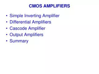
Presentation Agenda • High-Speed Amplifiers • Voltage Feedback vs. Current Feedback • Differential Amplifiers • Precision Amplifiers • AutoZero • Digitrim • Instrumentation and Industrial • High CMRR • VGA
High-Speed Amplifiers Voltage Feedback vs. Current Feedback Simplified Architecture Relationship Between Feedback and Bandwidth Stability
Error Voltage (V1) Amplified by the Open loop Gain (A) Closed Loop forces Error Voltage to be zero Error Current (i1) Amplified by the Transimpedance Gain (Z) Closed Loop forces the Error Current to be zero making the Input Voltages equal High Z High Z + + + Low Z Z(i1) A(V1) High Z V1 Ro - i1 - - Simplified Block DiagramsVoltage Feedback vs. Current Feedback Current Feedback (AD8014 or AD8007) Voltage Feedback (AD8039 or AD8092)
A(s) Loop Gain Gain [dB] Noise Gain f CL1 f CL2 RF RG + Voltage Feedback Frequency Response • Ideally Gain Bandwidth Product is constant • GBWP is more accurate for Higher Gains • GBWP is less accurate at Lower Gains due to peaking in the AC response • Intersection of Noise Gain and Open loop gain is the bandwidth of closed loop amplifier Frequency
Z(s) Impedance [W] Loop Gain Noise Gain f CL1 f CL2 RF RG Ro Z(S) + Current FeedbackFrequency Response • Intersection of Noise Gain and Open loop gain is the bandwidth of closed loop amplifier • Bandwidth is determined by the feedback network (RF and RO) • RO is typically between 20 and 40W Frequency
A(s) or Z(s) 180 225 270 PM=75° Phase Gain [dB] or Transimpedance (W) Degrees 315 PM=30° 360-0° Phase Margin 405 450 f CL1 f CL2 Frequency Stability AnalysisSame for Voltage and Current Feedback • Adjust Gain for phase margin > 45° for optimal operation • < 30° is unsafe
Differential Amplifiers Benefits of Differential Amplifiers Architectures of Differential Amplifiers Applications of Differential Amplifiers
Primary Uses for Differential Amps • Differential Signal Processing • Avoid Ground Noise • High Dynamic Range on Low Supplies • Differential Filters • High Speed ADC Driving • All High Speed ADC Perform Better when Driven Differentially • Amplify and Buffer DAC outputs • Differential Amplifiers Reduce Clock Jitter • Twisted-pair Line Driving/Receiving • Simplifies circuit design • Balanced Outputs Minimize EMI • High CMRR Reduces EMI Susceptibility
Benefits of Differential Signal Processing • Maximize Speed and Resolution with Differential Amps • Avoid Grounding/Return Noise Problems • Analog Signals in High-performance Systems Start and End Differential • Almost Always the Signal Source from the Real World is Differential • High-speed ADCs Have Differential Inputs • Better Distortion/Dynamic Range than Single-Ended Op-Amps • More Output Headroom for the same Signal Amplitude • Or Lower Distortion for the same output swing especially the 2nds
VS+ VOUT+ VOUT, Single ended + VOCM VOCM VOUT- - VOUT,Differential VS- High Speed Differential Amps for Challenging Designs • 3 Main Signal Characteristics of Differential Signals • Equal in amplitude, and opposite in phase • Differential Amplitude = 2x either Single Ended output • Centered at common voltage, VOCM
RF VOUT- + - RG VIN+ + - VOCM VIN- RG VOUT+ + - RF What’s Inside the Analog Devices Differential Amplifiers? • Internal CM Feedback forces Forces both outputs to be balanced • Equal in amplitude 180° out of phase: VOUT, CM = (VOUT+ + VOUT-)/2) • Balance is unaffected by RF/RG matching • Differential feedback effectively creates 2 summing nodes • Forces Both Inputs to the same voltage when the loop is closed • High Input Z, Low Output Z 3 5 8 2 1 4 6
More About the VOCM Pin • VOCM Pin • Creates Best Available Balance @ High Frequencies • By Forcing Outputs to be equal • For AC signals and DC Reference Voltages • For Easy Level Shifting • From Ground Referenced Signals (+/-5V supplies) to Single +5V Supply Signals
RF RG VIN VOUT- VOCM VOUT+ Understanding How They Work w/ Alternate Circuit Configurations Like Non-inverting Op Amp • 2 Feedback Loops • Differential feedback forces inputs to the same voltage • Common mode Feedback forces VOUT- = -VOUT+- • Non-inverting example: • For RF = 0 • VOut+ = VIN • Gain = 2 • Inverting example: • For RF = RG • High input Z summing node • Vout- = -VIN • Gain = 2 VIN VOUT- VOCM VOUT+ RF RG Like Inverting Op Amp
INOISE Single-ended Components Cannot Reject Ground Noise • Each Part of the Circuit Has a Different Reference Point • High Frequency Ground Currents will Cause Problems • Op Amp Can not Reject This Ground Noise VSIGNAL ZGND GND 2 GND 1
INOISE Differential Amps Have Effective CMRR • Differential Signal does not Need a Reference • Ground and Other Noise Sources are Common to Both Inputs • CMRR of Differential Amp is Effective VSIGNAL VOCM VOCM GND 1 ZGND GND 2
Driving High-Performance ADC on 5V Supply +5V +5 V 0.1 0.1 500 AVDD 50 DVDD 500 VINB + _ Digital AD9224 Outputs VOCM AD8138 VINA SENSE Source 0.1 50W AVSS DVSS CML 525 50 500 -5V • ADC Reference CML output drives VOCM to set optimum CM output • Easy level shift using VOCM • Better Distortion in signal chain for +/-5V, than +5V • Connect to the ADC reference or any other reference voltage
Cable Driving Challenge 1,000 ft. (300 m) CAT 5-UTP Want Transmitter plus Receiver Response to be Inverse of Cable 0 dB -20 dB @ 10 MHz Gain -60 dB @ 100 MHz 100kHz 1MHz 10MHz 100MHz Frequency
Balanced Driver Minimizes EMI Generation High CMRR Receiver Minimizes EMI Pick-up Vs+ 500W 500W Vs+ VfB AD8130 Vocm Vs- Vs- Differential Driver and Receiver
Auto-Zero Precision Amplifiers
Low Offset Voltage Less than 500uV Precision Amplifier Segments...Amplifier Characteristics Define Market Low Input Bias Current Less than 100pA Low Noise<5 nV/Hz <10 nV/Hz PRECISION AMPLIFIERS Rail-to-Rail In/Out Less than 100mV Low Voltage Less than 1.8V Less than 2.7V Low Power Less than 10uA Less than 500uA
Autozero Amplifiers: AD855x,AD857x families & AD8628 • 1mV of typical offset voltage (5mV max.) • 5 nV/°C of TCVOS from -40°C to +85°C • That’s less than 600 nV of drift over the entire temp. range • CMRR and PSRR are offset voltages due to changes in VCM and VSY • CMRR and PSRR are >135dB (or <0.3ppm) • 1/f noise, which increases at 3dB per octave decrease, can also be viewed as an offset error • The AD855x, AD857x and AD8628 exhibit NO 1/f noise!
Simplified Schematic of AD855x VOSB Main amplifier VIN+ + + AB VOUT - VIN- BB fB VNB CM2 VOA VOSA fB fA + + AA - -BA fA Nulling amplifier CM1 VNA
Spectral analysis of AD855x output in unity gain 4kHz auto-zero clock feedthrough 2nd harmonic from 4kHz Amplitude = 0.25mVRMS!
IMD+Noise Comparison Noise and auto-zero feedthrough are proportional to gain (duh…)
2nd Generation Auto-zero ampAD8628 World’s Highest Precision Amplifier • SOT-23 package !!! • Best noise ever for auto-zero--20nV/Hz • Like non-auto-zero amplifiers • Low Clock noise • 2.2MHz Gain-Bandwidth • No Compromise in auto-zero DC precision • 16 bits absolute accuracy: 0-10kHz—including noise Photodiodes, Portable scales, current sensors, IR sensors, strain bridges (pressure), remote sensors Release in April 2002
“Simplified” diagram of AD8628 amplifier Noise and auto-zero feedthrough are proportional to gain (duh…)
AD8628 Noise Spectral Density Comparison Noise and auto-zero feedthrough are proportional to gain (duh…)
Digitrim Precision Amplifiers
DigiTrim Amplifiers • Digitrim is a proprietary technology used to digitally adjust an in-package IC without adding any extra digital input pins • On the AD8601/2/4 family, DigiTrim adjusts offset voltage to <500mV • On the AD8603/7/9 family, DigiTrim adjusts offset voltage to <100mV • On the AD8605/6/8 family, DigiTrim adjusts offset voltage to <65mV
Advantages of DigiTrim • In-package trim • Mechanical stress on the die causes VOS errors • This can ruin any wafer trimming already done • Lots of stress on SOT23 and SC70 packages • By trimming in-package you trim out post-stress VOS! • No special processing - Foundry OK • As processing shrinks, trim area is smaller too • No extra pads required • Higher test throughput All this adds up to LOWER COST
V+ IT1 IT2 ID1 ID2 IN+ IN- I1 How is VOS trimmed? • Extra current is put into one side (or the other) of the input diff pair • This current difference creates an offset voltage between the diff pair transistors ID1 + ID2 = I1 IT1 or IT2 is adjusted to minimize VOS
AD8601/2/4 DigiTrim Amplifiers • VOS - < 500mV • Bandwidth - 8MHz • Input Bias Current - <60pA max. (<1pA typ) • DVOS/DT - 2mV/°C typ • Supply Current - 840mA/amplifier • SOT23 package (single) 10X Better than Standard CMOS!! A PC100 compliant Line Output Amplifier
Next Generation DigiTrim • AD8605/6/8Low noiseDigiTrim • Low noise—8nV/Hz • Low offset--65mV max! • Very low input bias current– 1pA max! • Fast--10MHz bandwidth • High CMRR, PSRR and Gain • Single in SOT23 and Wafer Level Chip-scale! • AD8603/7/9Low power/low noiseDigiTrim • Low Power--60mA per amplifier • Low offset--<100mV max • Low noise--30nV/Hz • 350kHz bandwidth • 1.8V to 5V operation Low Noise CMOS Release in April High Precision Low Power Photodiodes, Portable scales, current sensors, strain bridges (pressure), remote sensors
Top Core Applications • Photo-diode amp • Thermal sensing • Infrared • Thermocouples • RTD • Current sensing • Motor controls • Laser Diode Power Controls • Battery Controls • Strain Bridges • Level setting and detecting • Integrator
Photodiode trans-impedance amplifier Key Requirements Low input bias current Low Offset Voltage Low Drift Low Cin Bandwidth (Varies) Wide Dynamic Range Key Parts Requirements Vary depending on the Photodiode characteristics and the Data Acquisition System Requirements CMOS AD855X AD857X AD8601/2/4 AD8605/6/8 AD8628 AD8651
Key RequirementsLow Offset Voltage Low Input Current Low Drift High Input Impedance High Gain IR Thermal Sensing Key Parts Infra Red Sensor Auto-zero Amplifier CMOS AD855X AD857X AD8628 Amp IR Mux TMP Temp Reference mC A/D
Typical implementation (IR Thermal Sensing) Display Memory Digital Calibration uC AD Converter Micro-Controller
Low Side sensing with I sink AD8551 V(out) = (V+)- (R2/R1 * Rsense * IL) Features: Allows Sinking of current
High Side Sensing with current sink Monitor Output = R2 *(Rsense /R1) * IL Features : Great CMRR, very Low Vos ,Allows Sinking of Current
Instrumentation and Industrial Instrumentation Amplifiers Variable Gain Amplifiers
What is an Instrumentation Amplifier • It has many applications beyond instrumentation • Under the category of instrumentation amplifier, there are also: difference amplifier, HCMV amplifier, anddifferential-to-single ended amplifier • It could also be thought of as an IC with multiple op amps and laser trimmed resistors
What Does an Instrumentation Amplifier Do • Measures small precision signals in noisy environments • Rejects common mode voltage (noise) Vout = (Vin+ - Vin-) * gain
V1 R1 R2 - op-amp + Vout V2 R1 R2 Understanding the Difference Amplifier Architecture • When R1=R2 Vout = V2-V1 • When R1 R2 Vout = (V2-V1)*R2/R1
Difference Amplifiers Have High Common Mode Voltage Range • With Difference Amplifiers, the input voltage can be higher than the supply voltage. • This Difference Amplifier operates on +/-15V, gains the 20mV signal and rejects the +/-250V common-mode signal. AD629 20mV 250V
Difference Amplifier Application for Battery Charger • +/-500V Input Voltage Protection
Understanding the Instrumentation Amplifier Architecture • Difference Amplifier • BufferedInputs