Download
1 / 53
840 likes | 1.97k Views
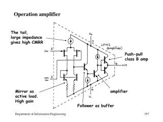
CMOS/SiGe BiCMOS 2.4GHz RF Linear Power Amplifier on PCB Module. 指導教授:劉致為 博士 學生:賴宏諱 台灣大學電子工程學研究所. Outline. Introduction Basic Concepts and Design Flow CMOS Power Amplifier SiGe BiCMOS Power Amplifier PCB Module Fabrication Summary. Outline. Introduction

E N D
CMOS/SiGe BiCMOS 2.4GHz RF Linear Power Amplifier on PCB Module 指導教授:劉致為 博士 學生:賴宏諱 台灣大學電子工程學研究所
Outline Introduction Basic Concepts and Design Flow CMOS Power Amplifier SiGe BiCMOS Power Amplifier PCB Module Fabrication Summary
Outline Introduction Basic Concepts and Design Flow CMOS Power Amplifier SiGe BiCMOS Power Amplifier PA Module Assembly Summary
Technology For PA Design In past, GaAs was the first choice for high frequency PA design because of high electron mobility and breakdown voltage. After technology improvement, more and more technologies are used.
Outline Introduction Basic Concepts and Design Flow CMOS Power Amplifier SiGe BiCMOS Power Amplifier PA Module Assembly Summary
Classification of Power Amplifier Linear: for non-constant envelope modulation (ex: OFDM) Class A : 100% duty cycle, effmax= 50% Class B : 50% duty cycle, effmax= 78.5% Class C : <50% duty cycle, effmax=78.5%~100% Class AB: 50%~100% duty cycle, effmax=50%~78.5% Nonlinear:for constant envelope modulation (ex: GMSK) Class D: ideal 100% efficiency Class E: ideal 100% efficiency Class F: ideal 100% efficiency
Linear Power Amplifier Vds=VDD+ids*ZLoad
Load Line Vin and iD swing Vo swing
∠ZLoad from 0o to 90o Vds=Idsx50∠30o →Vds leads more 30o to Ids
Inductive ZLoad Clockwise for inductive load
Capacitive ZLoad Counterclockwise for capacitive load
Outline Introduction Basic Concepts and Design Flow CMOS Power Amplifier SiGe BiCMOS Power Amplifier PA Module Assembly Summary
Schematic of 0.25um CMOS PA X4 X1 X6 X2 Unit Device : 64 fingers 10/0.25um RF NMOS VDD=3.3V
Circuit Layout Chip size : 0.98mm x 0.73mm=0.7154mm2
Measurement Current versus Pin for different VGS Output power and gain versus Pin Linear gain=26dB, P1dB=18.5dBm, Psat=21.8dBm Select VGS=1.1V, VDD=3.3V
Measurement IDC and PAE versus Pin S-parameters IDC=170mA, PAE@P1dB=13%, maximum PAE=23% At 2.45GHz, S11=-12.3dB, S22=-16.4dB, S12=-40.7dB
Schematic of 0.18um CMOS PA X1 X4 X2 X6 Unit Device : 64 fingers 2.5/0.18um RF NMOS VDD=2.5V
Simulation 1 dB compressed point→ +1.3dBm
Outline Introduction Basic Concepts and Design Flow CMOS Power Amplifier SiGe BiCMOS Power Amplifier PA Module Assembly Summary
Schematic of 0.35um SiGe PA Unit Device : hw153c2 (emitter:20.3um/0.9um) Vcc=3.3V, Q1:4X, Q2:16X, Q3:48X
Active Bias Circuit Linearity improvement
Active Bias Circuit Temperature Compensation
Circuit Layout Die size : 1.36mm x 0.68mm (0.9248mm2 )
Measurement Pout and gain versus Pin PAE and ICC versus Pin IDC=360mA,PAE@P1dB=15%, maximum PAE=24% Linear gain=27.6dB, P1dB=20.7dBm, Psat=25.4dBm
Measurement S-parameters Error Vector Magnitude Data rate=54Mbps, 64QAM OFDM At 2.45GHz, S11=-12.6dB, S22=-14dB, S12=-39.7dB
Spectrum Mask fc=2.45GHz,802.11b,11MB/s,CCK 802.11g,54MB/s, 64QAM OFDM Pout=15.2dBm (OFDM) Pout=17.8dBm (CCK)
Loop of Power Control Power detector senses present output power level and inform the controller by a corresponding DC voltage
Power Detector Circuit (I) Use BC junction for smaller capacitance. Added a diode to cancel DC offset caused by temperature variation.
Power Detector Circuit (II) Vi=VQ+Vaccosθ Ic=Isexp(VQ/VT)exp(Vaccosθ/VT) A DCcomponent can be extracted from the term exp(Vaccosθ/VT)
Dual Power Amplifier for IEEE 802.11n The main techniques multiply the data rate : (1) Spatial multiplexing (MIMO): 2 to 4 Tx/Rx. (2) Increasing the channel bandwidth: 2040 MHz/channel. (3) Increasing the constellation size: 64-QAM or Higher (4) Increasing the coding rate: (3/45/6 or 7/8) (5) Reducing the guard interval: (800ns400ns)
Dual Power Amplifier for IEEE 802.11n Die size : 1.98mm x 1.28mm (2.5344mm2 )
Outline Introduction Basic Concepts and Design Flow CMOS Power Amplifier SiGe BiCMOS Power Amplifier PA Module Assembly Summary
Load Pull System First, one tuner remains unchanged, and the other tuner varies to find the optimal impedance of maximum output power. Then the latter tuner keeps the optimal impedance, and the former tuner starts tuning. After iterated tuning, the optimal ZS and ZL are found.
Load Pull& TRL PCB Use load pull PCB to find optimal ZS and ZL for maximum power output 648mil 648mil Use TRL to eliminate effect of 344mil TL line. 344mil 344mil FR4 648mil/28mil TL line equals toλ/4 of 2.45GHz 344mil 344mil Die TRL PCB (Through, Reflect, Load) Load Pull PCB
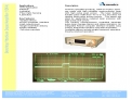
Matching PCB Photo of matched PA Module Matching PCB Passive Device: Murata SMD