Download

1 / 43
430 likes | 471 Views
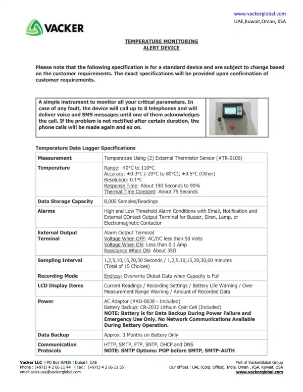
This Safety Monitoring Device and System (SMDS) project aims to develop a user-friendly monitoring system for detecting fires and explosions in commercial buildings, reducing response time, and integrating into existing security systems. Key components include thermal sensors, acoustic sensors, smoke sensors, and a microcontroller for data processing and communication. The system features a graphical user interface (GUI) for easy interaction, implemented with C# programming language in Microsoft Visual Studio 2008 environment. With emphasis on safety and efficiency, this project seeks to adhere to NFPA standards while providing reliable alert mechanisms through email and text messaging.

E N D
Safety Monitoring Device and System (SMDS)Sponsor: NovaComm Security Systems, INC. Senior Design II Summer 09 Group 7 Members: Alan Seims Andrew Farrell Frank Ogadah Tien Tran
Goals • Primary: Provide a user friendly monitoring system which can be used to detect fires and explosions in a commercial building • Purpose: • Reduce response time by rescue officials • Integrate into sponsors system: • Release emergency doors which have delays
System Requirements • Provide an area of coverage of 40’ x 40’ x 15’ • Detect incendiary events: • Room Temperature- Threshold set to 120˚F • Meet National Fire Protection Association(NFPA) standards “Low” under the category of heat detector. • Monitor room air for smoke • Detect explosions: • Room acoustic - Threshold set at 100dB(default) • Provide battery backup: 24 Hrs • GUI monitoring system for end user
Task Assignments • Controls – Frank Ogadah • User Interface – Tien Tran • Power Management - Alan Seims • Sensors - Andrew Farrell
Acoustic Sensor • Manufacturer : PCB Piezotronics • Model : 130D20 • Type: piezoelectric • Frequency response : 20Hz – 20kHz • pSPL(linear response) – 120dB • Cost: $420.00
Acoustic Circuit pSPL = 107.6dB
Thermal Sensor • National Semiconductor • Model: LM19 • Temperature range: -55˚C – 130˚C • Sensitivity: 11.9 mV/ ˚C • Tolerance: +/- 2.5˚C using a parabolic transfer function • Transfer Function: • Cost: $0.34
Smoke Sensor • Model: 276-142 • Matched IR Emitter/PhotoTransistor • Emitter: • λpeak = 850nm • Phototransistor • Spectral Bandwidth = 620nm - 950nm • Peak Sensitivity = 850nm • Cost: $3.49
Arduino Development • ATmega 328P Final Choice • 20 MIPS Throughput at 16 MHz • 6 Channel 10 Bit ADC PDIP (Input) • Programmable Serial USART • 13 Programmable Lines (I/O) • 6 Power Channels (PWM) • On chip analog comparator • Arduino IDE, C++ compatible
Communication(Sensors) Acoustic Sensor • Sensors send Analog Signals to Assigned pins • MCU will control Sensors via Digital Signals through Quad-High-Side-Switch • Sensors connected to LED to confirm activity • Communicate through FT232RL MCU ATMega328 Thermal Sensor Smoke Sensor
Communication(PC) CPU (GUI) • Receive communication from MCU • Transmit data via USB to Desktop • Have TX and RX LED to verify communication taking place (Optional) RS232 FT232RL USB CPU (GUI)
MCU Code Design • Used Arduino 0015 IDE • Program input and output pins • Program Function to collect & Display Analog Data • Control Function to Control Sensors
Software Development • GUI (Graphical User Interface), for easy user interaction • Language C# • Object Oriented programming • IDE – Microsoft Visual Studio 2008 • Provides very easy GUI creation tools and environments • Cost = Free from msdn
GUI Layout Start End • A class per form • Password Form start/ends program • System Log updates at for each event • Verifies user has correct access to use the system • Branches to Main Form if successful Password Form Verify Account Main Form
GUI Layout • Main form branches to 5 other forms • Monitor and Alert deals with microcontroller and outside contact • System Log is updated automatically at certain events • Admin rights determines ability to modify EContact and UserAccount data • New editing or adding new entry Alert Form Main Form System Log Form Monitor Form Admin Check Emergency Contact Form User Account Form Add/Edit Form Add/Edit Form
Database • 3 Text files for storing specific system information • UserAccount.txt – Holds user account info • EContacts.txt – Hold emergency contact information • SystemLog.txt – Holds log data for specific events occurring during operation
Data Size Consumption • UserAccount.txt – 174 bytes/Entry • 20 X 174 = 3480 bytes or 3.4 kilobytes • EContacts.txt - 134 bytes/Entry • 20 X 134 = 2680 bytes or 2.62 kilobytes • SystemLog.txt – 115 bytes/Entry • (4-logs X 2-instances X 365-days) X 115 bytes = 335800 bytes or 327.9 KB or .32 MB • Cheapest and smallest HD 160 GB for $30 Newegg
Alert Design • Alert Form • Sends important messages to selected individuals • Message is dictated by user • Update log • Uses data from EContact.txt • Two forms of alert: • Email • Text messaging
Alert Design Start • Execution tier: • Email • Text message • Cycle through each contact entry and checks priority and executes based on priority • Priority levels: 1 - 3 Match Priority Next Entry Send Email Check if Texting Send Text Message
Alert Design • Use smtp mail server to send out email and text message • Requires an account with username and password • Demonstration: Smtp from Google using GMAIL • smtp.gmail.com, port 587
Alert Design • Email • Subject, Message, Email Address • Text Messaging • Subject, Message, Cell Phone Number • Gateway • AT&T Wireless: number@txt.att.net • T-Mobile: phonenumber@tmomail.net • Verizon: phonenumber@vtext.com
Device Monitor Design • Monitor Form class • Connects to detection device, serial • Turn off individual sensors or resets them all • Monitors signals transferred from device • Shows message when sensors are tripped with visual representation • Call alert from this form
Power Management and Distribution System • The device requires a continuous supply of at least 24 VDC. • The system has two power sources: main power supply and battery backup. • Battery Backup provides 24-Hr run time • Power to each sensor is controlled by the Central Monitoring System.
Main Power Source: LS35-36 • Switch-mode power supply • 50 kHz switching frequency • 88-264 VAC/47-63 Hz input • Provides 36 VDC at 1 A • Small size (3.9” x 3.2” x 1.4”) • Cost: $19.03
Battery Backup Source • Ensures uninterrupted power to the device for 24-Hrs. • Two PS-1221S 12 V SLA batteries in series. • 2 Ah capacity • 5.75” x 3.5” x .75” • 1.5 lb ea. • Cost: $22.95 ea.
Battery Charging System: UC3906 • Designed specifically for Sealed Lead Acid Batteries • Programmable charge current • Used as a three level float charger • 16 pin DIP IC ( .785”x.3” ) • Input voltage range: 6-40 V • Cost: $5.50
Sensor Power Control: LT1161 • Solid state switch compared to electro-mechanical relay. • 20 lead plastic DIP • Enables the Central Monitoring System to control sensor power. • Input voltage: 8-48 V • Fully enhances N-channel MOSFET switches • Individual short circuit protection for the sensors • Cost: Free
Voltage Regulators: LM317M • Adjustable voltage through the use of an external voltage divider circuit • Output voltage: 1.2-37 V • Output current: .5 A • Cost: $.69 ea.
Physical Testing • System Testing: • Acoustic: Cap gun to generate a sound pressure wave greater than 100dB • Thermal Detector: use a heat gun • Smoke: Use a fire detector test spray which met • NFPA standard 72 • UL Standards 217 and 268 • Battery Backup: disconnect main power and test. • Software testing: • Proper alerts were executed