Download

1 / 10
100 likes | 117 Views
Learn how Kirchoff’s Laws help determine current flow in circuits, with equations and concepts explained for easy understanding. Solve circuit problems using Kirchoff's Laws and practice with examples.

E N D
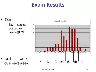
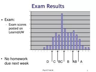
Exam 1 Results Small curve: Score based out of 78 points Plan to reweight final grades as follows: Lowest exam grade: 5% Other 2 exams: 11% each
Kirchoff’s Laws – I1 + I2 – + I3 12 V • Kirchoff’s Laws help us figure out where and how much current is flowing in a circuit • The first step is to assign a direction and a current to every part of a circuit • Items in series must have the same current in them • Then you apply the two laws, which can be thought of as conservation of charge and conservation of voltage, which you apply to vertices and loops respectively. 3 5 6 V Kirchoff’s First Law: The total current into any node equals the current out of that node 4 Kirchoff’s Second Law: The total voltage change around a loop is always zero • These yield a series of equations, which you then solve
Kirchoff’s First Law – I1 + I2 – + I3 12 V Kirchoff’s First Law: The total current into any node equals the current out of that node 3 • A node is any place where three or more wires come together • For example, at point A, this gives the equation: • At point B, this gives the equation: B A 5 6 V 4 You always get one redundant equation
Kirchoff’s Second Law – I1 + I2 – + I3 12 V Kirchoff’s Second Law: The total voltage change around a loop is always zero • First, pick a direction for everyloop • I always pick clockwise • Start anywhere, and set 0 equal to sum of potential change from each piece: • For batteries: V = E • It is an increase if you go from – to + • It is a decrease if you go from + to – • For resistors: V = IR • It is a decrease if you go with the current • It is an increase if you go against the current 3 5 6 V 4
Concept Question – I1 + I2 – + I3 12 V Kirchoff’s Second Law: The total voltage change around a loop is always zero • First, pick a direction for everyloop • I always pick clockwise • Start anywhere, and set 0 equal to sum of potential change from each piece: • For batteries: V = E • It is an increase if you go from – to + • It is a decrease if you go from + to – • For resistors: V = IR • It is a decrease if you go with the current • It is an increase if you go against the current 3 5 6 V 4 Tophat
Kirchoff’s Law- Final Step – I1 + I2 – + I3 12 V • You have derived three equations in three unknowns 3 • We now solve these simultaneously • We can let Maple do it for us if we want: A 5 6 V > solve({i3=i1+i2,0=-5*i2-6.-4*i3,0=18-3*i1+5*i2},[i1,i2,i3]); 4 • Negative currents mean we guessed the wrong way • Not a problem
Kirchoff’s Laws with Capacitors + + + – – – Q • Pick one side to put the charge on • The voltage change is given by V = Q/C • It is a decrease if Q is the side you are going in • It is an increase if Q is the side you are going out • The current is related to the time change of Q • Add a minus sign if I isn’t on the same side as Q • If you are in a steady state, the current through a capacitor is always zero C In this circuit, in the steady state, where is current flowing? It’s really just a battery and two resistors in series!
The Simplest RC Circuit I R Q0 In the circuit shown at left, the capacitor starts with charge Q0. At time t = 0, the switch is closed. What happens to the charge Q? C • Current begins to flow around the loop, so the charge Q will change • This is a differential equation, and therefore hard to solve Check the units:
Charging and Discharging Capacitors Q I R C E + – • The combination RC = is called the time constant • It’s the characteristic time it takes to discharge • We can work out the current from In this circuit, the capacitor is initially uncharged, but at t = 0 the switch is closed. What happens?
Ammeters and Voltmeters V A • An ammeter is a device that measures the current (amps) anywhere in a circuit • To use it, you must route the current through it • A perfect ammeter should have zero resistance • A voltmeter is a device that measures the potential difference (volts) between any two points in a circuit • To use it, you can simply connect to any two points • A perfect voltmeter has infinite resistance