Download
1 / 33
330 likes | 342 Views
This study explores energy transmutation and the Kvinta setup through simulations and experiments at the Nuclear Physics Institute. The setup, methods, results, and conclusions are detailed.

E N D
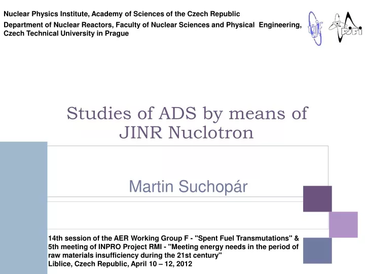
Nuclear Physics Institute, Academy of Sciences of the Czech Republic Department of Nuclear Reactors, Faculty of Nuclear Sciences andPhysical Engineering, Czech Technical University in Prague Martin Suchopár Studies of ADS by means of JINR Nuclotron 14th session of the AER Working Group F - "Spent Fuel Transmutations"& 5th meeting of INPRO Project RMI - "Meeting energy needs in the period of raw materials insufficiency during the 21st century" Liblice, Czech Republic, April 10 – 12, 2012
Outline • Energy + Transmutation & Kvinta setup description • Method and models used in MCNPX simulations • Computation results • Beam monitoring and cross-section measurement • Conclusion Setup Method Results Beam monitors Conclusion
Energy + TransmutationSetup • Setup • E+T setup • Kvinta setup • Method • Results • Beam monitors • Conclusion m natU = 206 kg
Kvinta 2010 and 2011 Setup Kvinta 2010 setup Kvinta 2011 setup • Setup • E+T setup • Kvinta setup • Method • Results • Beam monitors • Conclusion • 3 sections • 4 detector plates • Pb shielding • 5 sections • 6 detector plates • no Pb shielding m natU = 315 kg m natU = 512 kg
Kvinta-M 2011 Setup • Setup • E+T setup • Kvinta setup • Method • Results • Beam monitors • Conclusion
Y Target sections (U-238) 114 120 p, d Z 0 r 40 Beam window, Ø 80 17 17 17 17 131 262 393 524 655 700 Kvinta-M 2011 Setup March 2011 irradiation • Setup • E+T setup • Kvinta setup • Method • Results • Beam monitors • Conclusion 6
Y beam entrance window 150×150 mm mounting pits for detector plates 114 120 Z 0 r 40 d section U-238 17 131 17 17 17 262 lead shielding 100 mm 393 524 655 700 900 Kvinta-M 2011 Setup • Setup • E+T setup • Kvinta setup • Method • Results • Beam monitors • Conclusion December 2011 irradiation 7
Kvinta-M 2011 Setup • Setup • E+T setup • Kvinta setup • Method • Results • Beam monitors • Conclusion
Energy + Transmutation and Kvinta Irradiations • Setup • E+T setup • Kvinta setup • Irradiations • Method • Results • Beam monitors • Conclusion 9
QUINTA-M setup layout at the irradiation position Detector plates Target«Quinta-М» Pad with Pb foil monitor and SSNTD Plate (700х400х16) Platform Beam window Rails p, d SSNTD and AD positions on the QUINTA-M target surface • Setup • E+T setup • Kvinta setup • Irradiations • Method • Results • Beam monitors • Conclusion 10
QUINTA setup and equipment layout during an experiment at F-3 focus (December 2011) Sc telescope 3320 Platform (turned by 2°relatively to the beam axis) Profilometer QUINTA Activation foil Ionization chamber 20° 160° 90° 2 detectors Demon (NE213) Beam extraction 2 detectors Demon (NE213) Polyethylene shielding 2 detectors Demon (NE213) ISOMER detectorНе3 • Activation detectors • Solid State Track detectors • NE213, Stilben neutron detectors • He-3 neutron detectors • Setup • E+T setup • Kvinta setup • Irradiations • Method • Results • Beam monitors • Conclusion 11
Main Objectives of the Kvinta Setup • To have another set-up for benchmark studies of neutron production and transport simulation codes (e.g. MCNPX code) • To have systematic of deuteron beams with energies above 1 GeV • To obtain strong source of neutrons for transmutation tests • Measurement of neutrons and delayed neutrons during low intensity beam irradiation by scintillation detectors • Measurement of neutron field during high intensity beam irradiation by threshold activation and solid state track detectors • Measurement of fission yields in thorium and natural uranium samples in fast neutron spectra • Setup • E+T setup • Kvinta setup • Irradiations • Method • Results • Beam monitors • Conclusion 12
Comparison of E+T and Kvinta Setup E + T setup model Kvinta 2011 setup model • Setup • Method • Setup model • MCNPX simulation • Results • Beam monitors • Conclusion 30 U rods 54 U rods 61 U rods
Kvinta Setup with Lead Shielding Kvinta 2012 setup model • Setup • Method • Setup model • MCNPX simulation • Results • Beam monitors • Conclusion front view 54 U rods 61 U rods side view top view 14
MCNPX simulations • Setup • Method • Setup model • MCNPX simulation • Results • Beam monitors • Conclusion • Used version MCNPX 2.7a • Used Los Alamos la150n and la150h libraries • All available physics models tested • Most preferred combination of models – Bertini-Dresner (default) and INCL-ABLA (time-consuming computation but provides the most reliable results)
Kvintaneutron spectra Kvinta setup with Pb shielding simulated neutron spectra in Al foil • Setup • Method • Results • neutron spectra • neutron distribution • MCNPX models • Multiplicity in various models • Beam monitors • Conclusion
Kvintaneutron distribution Kvinta setup with Pb shielding 24Na yield in Al foils distribution in 4 GeV deuteron experiment • Setup • Method • Results • neutron spectra • neutron distribution • MCNPX models • Multiplicity in various models • Beam monitors • Conclusion simulated and experimental yield per source deuteron per gram of activation material
Kvintaneutron distribution Kvinta setup with Pb shielding longitudinal neutron distribution • Setup • Method • Results • neutron spectra • neutron distribution • MCNPX models • Multiplicity in various models • Beam monitors • Conclusion normalization to the Al foil located on the target axis on the second detector plate
Kvintaneutron distribution Kvinta setup with Pb shielding radial neutron distribution • Setup • Method • Results • neutron spectra • neutron distribution • MCNPX models • Multiplicity in various models • Beam monitors • Conclusion normalization to the Al foil located on the target axis on the second detector plate
Simulated multiplicity – various models Kvinta 5 sections setup neutron multiplicity • Setup • Method • Results • neutron spectra • neutron distribution • MCNPX models • Multiplicity in various models • Beam monitors • Conclusion
Simulated multiplicity – various models Kvinta 5 sections setup with Pb shielding neutron multiplicity • Setup • Method • Results • neutron spectra • neutron distribution • MCNPX models • Multiplicity in various models • Beam monitors • Conclusion
Simulated multiplicity – various models Kvinta 5 sections setup neutron multiplicity per GeV • Setup • Method • Results • neutron spectra • neutron distribution • MCNPX models • Multiplicity in various models • Beam monitors • Conclusion
Simulated multiplicity – various models Kvinta 5 sections setup with Pb shielding neutron multiplicity per GeV • Setup • Method • Results • neutron spectra • neutron distribution • MCNPX models • Multiplicity in various models • Beam monitors • Conclusion
Simulated multiplicity – various models Comparison of Kvinta 5 sections setup with and without Pb shielding neutron multiplicity • Setup • Method • Results • neutron spectra • neutron distribution • MCNPX models • Multiplicity in various models • Beam monitors • Conclusion
Simulated multiplicity – various models Comparison of Kvinta 5 sections setup with and without Pb shielding neutron multiplicity per GeV • Setup • Method • Results • neutron spectra • neutron distribution • MCNPX models • Multiplicity in various models • Beam monitors • Conclusion
Neutron multiplicityfrom various models • Setup • Method • Results • neutron spectra • neutron distribution • MCNPX models • Multiplicity in various models • Beam monitors • Conclusion
Neutron multiplicityfrom various models • Setup • Method • Results • neutron spectra • neutron distribution • MCNPX models • Multiplicity in various models • Beam monitors • Conclusion 27
Beam Monitoring and xs Measurements • deuteron beam with energies of 1, 2, 4 and 6 GeV • common measurement of beam intensity using ionization chambers • aluminium and copper foils for beam monitoring • aluminium foil – integral number of deuterons determination, placed several meters away from the set-up • copper foil – deuteron cross-section measurement, placed together with the aluminium foil • copper foil cut into pieces – beam position and profiledetermination, placed directly on the beginning of the target • gold foil with aluminium standard – deuteron cross-section measurement, used in the most recent experiments (1 and 4 GeV) • copper foil – beam alignment with the target axis, placed on the back of the target (2, 4, 6 GeV experiments without Pb shielding) Setup Method Results Beam monitors Conclusion
Beam Monitors Self-absorption correction Beam instability correction Square-emitter correction Decay during cooling and measurement Peak area g line –intensity per decay Detector efficiency Correction for geometry change Correction for Coincidences Dead time correction Decay during irradiation Beam integral determination by Al foil Setup Method Results Beam monitors Conclusion λ – decay constant, tirr – irradiation time, treal – real measurement time, tlive – live time of the detector, t0 – cooling time. 29
Beam Monitors Setup Method Results Beam monitors Conclusion Nyield – total amount of produced 24Na nuclei, A – molar weight, σ - cross-section, m – weight of the foil, S – area of the foil, NA – Avogadro’s number. 30
Beam Monitors Setup Method Results Beam monitors Conclusion Cu foil cut into 16 pieces 2x2 cm 4 most active foils cut again into 16 pieces 1x1 cm example of beam position and shape determination (6 GeV exp) results from SSNTD (A. Potapenko) results from activation foils (Řež group) 31
Conclusion Setup Method Results Beam monitors Conclusion • made detailed model of the new Kvinta setup consisting of uranium target and blanket • calculated neutron multiplicity of several modifications of the new Kvinta setup • simulated neutron spectra in diverse positions in the new Kvinta setup and obtained experiment/simulation yield ratios • studied dependency on various physics models included in MCNPX • performed beam integral, position, shape and alignment monitoring using aluminium and copper foils • performed deuteron cross-section measurements on copper and gold foils, data in evaluation process 32