Download
1 / 18
180 likes | 325 Views
Cen /TC226/WG1/CME 16° meeting agenda. Welcome. Matters arising from 15th meeting in Stockholm 21st May 2007. Marco CME Membership Trevor, Marco LS Dyna latest developments – report from LSTC. Marco TNO project on the interaction of lighting columns & soil Peter de Coo

E N D
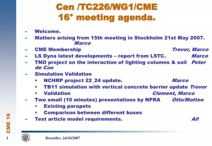
Cen /TC226/WG1/CME 16° meeting agenda. • Welcome. • Matters arising from 15th meeting in Stockholm 21st May 2007. Marco • CME Membership Trevor, Marco • LS Dyna latest developments – report from LSTC. Marco • TNO project on the interaction of lighting columns & soil Peter de Coo • Simulation Validation • NCHRP project 22_24 update. Marco • TB11 simulation with vertical concrete barrier update Trevor • Validation Clement, Marco • Two small (10 minutes) presentations by NPRA Otto/Matteo • Existing parapets • Comparison between different buses • Test article model requirements. All 1 Bruxelles. 24/10/2007
New member • Fracasso nominated Miss Claudia Cofano as observer. • Introduction 2 Bruxelles. 24/10/2007
TRB report • COE meeting at LSTC on August 3-5 • New material model. 3 Bruxelles. 24/10/2007
New material. • Elasto-plastic isotropic material with piecewise plasticity and strain rate sensititvity (similar to MAT_024). • Element elimination based on a new theory refining Jonson Cook model. 4 Bruxelles. 24/10/2007
Material constituive law Stress: Using principal stresses: Ordinate so that: 5 Bruxelles. 24/10/2007
And: 6 Bruxelles. 24/10/2007
Define: 7 Bruxelles. 24/10/2007
In plane stress. 8 Bruxelles. 24/10/2007
εplastic failure 1/3 -1/3 0 -2/3 2/3 Compression tri axial Tension biaxial Tension mono axial Tension tri axial Compression mono axial Compression bi axial Pure shear 9 Bruxelles. 24/10/2007
NCHRP 22_24 • Survey of validation techniques in different fields. • Survey of modelling techniques: • http://www.surveymonkey.com/s.aspx?sm=KMKyPxAII8B3GWYwJ2R0Dg_3d_3d • First official meeting in January 10. After this date first documents will be delivered. 10 Bruxelles. 24/10/2007
Validation based on velocity comparison. • Accelerometers comparison does not fit for objective validation method. • Global reference frame velocity comparison. • Rotations of accelerations (unfiltered). • Evaluation of global reference frame velocities. • Different requirements in different directions? 11 Bruxelles. 24/10/2007
All RR tests. • Same rigid barrier. • Different vehicles. • 12 tests 12 Bruxelles. 24/10/2007
Validation based on velocity comparison. • To take into account the different importance of components, validation based on resultant velocity. • After the point where the difference between simulated and measured resultant velocity is greater than: • Xx% of current velocity (suggestion:± 5% of initial current velocity)? • Xx% of initial velocity (suggestion:± 5% of initial velocity)? The model is no longer validated. 13 Bruxelles. 24/10/2007
Comparison based on resultant velocity. 14 Bruxelles. 24/10/2007
Validation. All requirements. • Severity indices: • ASI THIV • Barrier behavior. • Deformation (WW, DD). • Failures (number and location). • Vehicle: • Trajectories. • Failures ? (during RR different failures) • Resultant velocity. • Yaw rate 15 Bruxelles. 24/10/2007
Validation. • To proceed we must define limits for the above criteria. • Than: • Severity indices: • ASI THIV • Barrier behavior. • Deformation (WW, DD). • Failures (number and location). • Vehicle: • Trajectories. • Failures ? (during RR different failures) • Resultant velocity. • Yaw rate. 16 Bruxelles. 24/10/2007
Test article model requirements. • All components of the test article must be modeled. • Failure modes must be include in the model. • If failure modes are not explicitly described “sensors” must be used to verify that these elements are far from failure. • According to the energy to be transferred and to the design philosophy critical components must be identified. 17 Bruxelles. 24/10/2007
Test article model tests. • Failures in the test item shall be demonstrated. • Failure description can be reported using already existing experience. • The function of non-critical components: Suitable engineering analysis can be used to demonstrate model performance, particularly where the component is not a weak point in the structure • Influence of loading speed must be considered. • All failed and strongly deformed components shall be reproduced using simulation and validated by component test. 18 Bruxelles. 24/10/2007