Download
1 / 18
180 likes | 297 Views
SNAP CCD Development Progress. Hakeem Oluseyi January 9, 2003. Development Team. LBNL Physics/Astrophysics C. Bebek, M. Levi, H. Oluseyi, S. Perlmutter, V. Prasad LBNL Engineering J. Bercovitz, A. Karcher, W. Kolbe LBNL Microsystems Laboratory S. Holland, N. Palaio, G. Wang

E N D
SNAP CCD Development Progress Hakeem Oluseyi January 9, 2003
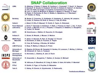
Development Team LBNL Physics/Astrophysics C. Bebek, M. Levi, H. Oluseyi, S. Perlmutter, V. Prasad LBNL Engineering J. Bercovitz, A. Karcher, W. Kolbe LBNL Microsystems Laboratory S. Holland, N. Palaio, G. Wang Student Interns H. Bertsch, S. Farid, M. Wagner
Outline • Motivation and Technology • Commercialization of CCD Technology • Precision 4-Side Buttable Packaging • Characterization Results • Summary
Guider HgCdTe CCDs Spectrograph Spectrograph port rin=6.0 mrad; rout=13.0 mrad rin=129.120 mm; rout=283.564 mm SNAP SNAP CCD Design Drivers • Wavelength Response • Plate Scale/PSF • Radiation Tolerance • HgCdTe Area Match
Outline • Motivation and Technology • Commercialization of CCD Technology • Precision 4-Side Buttable Packaging • Characterization Results • Summary
LBNL MicroSystems Laboratory CCD’s fabricated at LBNL Microsystems Laboratory Commercialization efforts at CCD foundry in progress Thermco furnaces at LBNL Microsystems Laboratory 150 mm Lithography tool at LBNL Microsystems Laboratory
Commercially fabricated 150 mm wafer 150 mm DALSA-fabbed wafer. Large rectangular devices are 2k x 4k, 15 mm; large square devices are 2.8k x 2.8k, 10.5 mm with 4-corner readout. Front-illuminated 2k x 4k (15mm pixel) Back-illumination technology development in progress Fabrication at Dalsa Semiconductor (formerly Mitel)
Outline • Motivation and Technology • Commercialization of CCD Technology • Precision 4-Side Buttable Packaging • Characterization Results • Summary
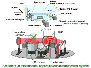
CCD Assembly and Test • Established a factory to reliably package devices: • With reliable connectivity (wire-bonding) • Without damage to optically active surface • Without ESD damage • Without excessive mechanical stress on CCD • Packaging status: • Used LBNL speckle interferometer to study detector distortion due to differential CTE of CCD, substrate, and moly mount. • About a dozen configurations have been studied. • Thick AlN looks acceptable for now. • Future: • CCD mounted to a “thick” silicon substrate is the preferred solution to minimize stress in CCD. • We will explore the elimination of wire-bonds and support of the CCD over its entire area. Speckle interferograph – excursions within 6 mm.
Outline • Motivation and Technology • Commercialization of CCD Technology • Precision 4-Side Buttable Packaging • Characterization Results • Summary
Pixel size Well depth Linearity Dark current Sensitivity Persistence Read noise Quantum efficiency Charge transfer efficiency CTE radiation degradation Diffusion Intrapixel response Radiation Proton when irradiated cold 60Co when cold Heavy ion study Fabrication Packaging 10.5 m devices work, need more experience. 130 ke– for 10.5 m pixel. Better than 1%. 2 e–/hr/pixel. 3.5 mV/e– Erase mechanism is effective. 2 e–. Extended red performance realized. CTI ~ 10-6 pre-irradiation. 1.5x10⁻¹³ g/MeV-cm2 On-going study. On-going study. More robust than existing space devices when damaged warm. No surprises. An activity during the next 6 months. Partially commercialized. Underway LBNL CCD Performance R&D areas.
QE & Noise Performance 2 layer anti-reflection coating: ~ 600A ITO, ~1000A SiO2
Radiation Tolerance CTE is measured using the 55Fe X-ray method at 128 K. The readout speed is 30 kHz, the X-ray density is 0.015/pixel. Degradation is about 110-13 g/MeV. [1]L.Cawley, C.Hanley, “WFC3 Detector Characterization Report #1: CCD44 Radiation Test Results,” Space Telescope Science Institute Instrument Science Report WFC3 2000-05, Oct.2000 [2] T. Hardy, R. Murowinski, M.J. Deen, “Charge transfer efficiency in proton damaged CCDs,” IEEE Trans. Nucl. Sci., 45(2), pp. 154-163, April 1998
PSF Results • Spatial resolution limited by diffusion of photogenerated carriers during drift from generation point to CCD potential wells • Key issue for SNAP: Desire for small pixel sizes requires spatial resolution consistent with pixel size • Major ramifications on technology development and devicedesign VSUB= 20V VSUB= 60V 1100 x 800 back-illuminated CCD, 15 mm pixels
Summary • Fully depleted, back-illuminated CCD technology • Device physics • Fabrication at LBNL and commercially • Spatial resolution • Use at telescopes • On-going efforts • Deployment of more CCD’s at telescopes • Completing 4-side buttable packaging • CCD Development for SNAP • Moving towards “Volume” manufacturing • Proton damage studies (June 2002 IEEE Trans. Nucl. Sci., Jan ‘02 SPIE) • Good spatial resolution and small pixel size • 10.5mm pixels with PSF ~ 4mm s • Higher voltages/thinner wafers