Download
1 / 41
410 likes | 452 Views
Explore Fermilab's cutting-edge Project-X, enhancing the energy and intensity frontiers of particle physics with advanced technologies and collaborative research ventures.

E N D
High Intensity SRF Proton Accelerator at Fermilab:Project-X Shekhar Mishra ILC, Project-X & SRF Program Fermilab
Fermilab Long Range Plan • Fermilab is the sole remaining U.S. laboratory providing facilities in support of accelerator-based Elementary Particle Physics. • The Fermilab long-term • Strategy is to provide world • Leading Accelerator facilities • Supporting forefront research • at the Energy and Intensity • Frontiers • - Consistent with the HEPAP/P5
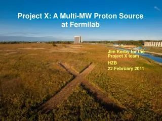
Evolution of the Accelerator Complex • A multi-MW Proton Source, Project-X, is the main part of Fermilab’s strategy for future development of the accelerator complex. • Project-X is designed to provide flexibility in evolving Fermilab program in response to research results anticipated around 2013 • Energy Frontier: • Tevatron ILC or Muon Collider • Technology alignment • Project-X development retains ILC and MC as options for the Fermilab site • Intensity Frontier: • NuMI NOvA LBNE/mu2e multi-MW Proton Source NuFact • Continuously evolving world leading program in neutrino physics and other beyond the standard model phenomena
Near Term Strategy • Project X is moving through the DOE system in coordination with the Long Baseline Neutrino Experiment (LBNE) and the muon to electron conversion experiment (Mu2e) • LBNE and Mu2e will both establish mission need (CD-0) on the basis of modest upgrades to the existing complex. • Both have been told to expect CD-0 “shortly”, and to be prepared for CD-1 at the end of FY2010. • The Project-X mission will be to provide significant extension of the reach of these two initiatives, while simultaneously creating a broader range of intensity frontier opportunities. • Several briefings for the Office of Science on strategy, including to Brinkman by Pier on Aug 13th. • CD-0 for LBNE and Mu2e are pre-requisites to CD-0 for Project-X
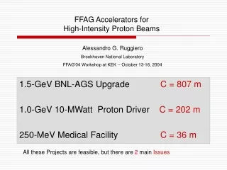
Initial Configuration -1 • Project X Design Criteria • 2 MW of beam power over the range 60 – 120 GeV • Simultaneous with at least 150 kW of beam power at 8 GeV • Compatibility with future upgrades to 2-4 MW at 8 GeV.
Modulator Modulator Modulator Modulator Modulator Modulator Modulator Modulator Modulator Modulator Modulator Modulator Modulator Modulator Modulator Modulator Modulator Modulator Modulator Modulator Modulator Modulator Modulator Modulator Modulator =0.8 ILC ILC ILC ILC ILC ILC ILC =0.8 =0.8 ILC ILC ILC ILC ILC ILC ILC ILC ILC ILC ILC ILC =0.8 =0.8 ILC ILC ILC ILC ILC ILC ILC ILC ILC ILC ILC ILC ILC ILC =0.8 ILC ILC ILC ILC =0.8 =0.8 ILC Front End Linac Project X 1000 kW 8GeV Linac • 325 MHz 0-10 MeV • 1 Klystron (JPARC 2.5 MW) • 16 RT Cavities • 325 MHz 10-120 MeV • 1 Klystron (JPARC 2.5 MW) • 51 Single Spoke Resonators • 5 Cryomodules 2.5 MW JPARC Klystron Modulator Modulator 28 Klystrons (2 types) 461 SC Cavities 58 Cryomodules Multi-Cavity Fanout Phase and Amplitude Control H- RFQ RT SSR1 SSR1 SSR2 SSR2 SSR2 9 or 11 Cavites / Cryomodule Modulator 325 MHz0.12-0.42 GeV 3 Klystrons (JPARC 2.5 MW) 42 Triple Spoke Resonators 7 Cryomodules TSR TSR TSR TSR TSR TSR TSR 6 Cavites-6 quads / Cryomodule 1300 MHz LINAC 1300 MHz0.42-1.3 GeV 4 Klystrons (ILC 10 MW MBK) 64 Squeezed Cavities ( b=0.81) 8 Cryomodules 1300 MHz1.3-8.0 GeV 19 Klystrons (ILC 10 MW MBK) 304 ILC-identical Cavities 38 ILC-like Cryomodules
Initial Configuration - 2 • Project X Design Criteria • 2 MW of beam power over the range 60 – 120 GeV • Simultaneous with at least 150 kW of beam power at 8 GeV • Compatibility with future upgrades to 2-4 MW at 8 GeV.
SRF Development • Regardless of which configuration is selected a considerable amount of SRF development is needed to support Project-X. • Fermilab with collaborating US and International laboratories is doing a considerable SRF R&D and infrastructure development • We are expecting that the construction will take about 3-4 years. DOE Site Visit
SRF Collaborations • ANL: EP development and cavity processing • Cornell: Cavity processing & test, materials R&D • DESY: 3.9 GHz, cryomodule kit, FLASH, S0 R&D • KEK: Cavity R&D, ATF II, S0 R&D • MSU: Px Beta=0.8 cavities, hydroform, TIG • TJNL: EP cavity processing and test, S0 R&D • INFN: tuners, HTS, NML gun cathodes • TRIUMF: Vendor development • SLAC: RF power, klystrons, couplers, distribution • CERN, DESY, KEK, INFN, etc: Type IV CM design • India: CM design, Px Beta= 0.8 cavities, infrastructure, etc • China: Peking U, IHEP, cavity development • UC,NW,NHMFL, Cornell, DESY, KEK, etc: SRF Materials
Scope of R&D and Infrastructure Development • Cavity Gradient Goal: Master cavity processing & handling to achieve 35 MV/M gradient with 80% yield on 1st try, 90% yield after 2nd • Project X: 1 CM/month = 96 good cavities a year ( > 25 MV/M) • Requires U.S. vendors capable of fabricating 100 cavities/yr • Laboratory/industrial processing and test capability able to handle >200 process/test cycles per year (ANL, FNAL, JLAB) • Drives scope of planned ANL/JLAB EP and FNAL VTS upgrades • Drives the need for SRF materials and surface studies • Project X & ILC R&D Goals: Cavity, Cryomodule and RF Unit test goals: • Require infrastructure to dress and HTS test cavities • Require infrastructure to build ILC Cryomodules at 1/month • Require infrastructure to test individual cryomodules • Require infrastructure to test Px or ILC RF units (NML) • Large overlap in Project X and ILC R&D 1.3 GHz program needs
SRF Infrastructure Plan FY08 Omnibus delayed our plan (financially) and affected our work force (still recovering personnel) Nevertheless very measurable progress on facilities Plan based on $25M/yr (SRF B&R) for FY10 through FY13 plus the ARRA funds ($52.67M total)
Nb Cryomodule • Niobium purchased from Industry • Nb QA/QC at Fermilab • Cavity Fabricated by Industry • Cavity QA/QC at Fermilab • Cavity Processed and tested at Jlab, Cornell, ANL/FNAL • We are working to transfer the processing to industry • Cavity Dressed (He vessel, Tuner, Coupler) at FNAL • This will be transferred to industy • High Power Test at FNAL • Cavity String and Cryomodule Fabrication at FNAL • Cryomodule Testing at FNAL
1.3 GHz Joint Development Strategy Project X shares 1.3 GHz technology with the ILC Project X requires 46 ILC-like cryomodules. In detail they will not be identical to ILC: Beam current: 20 mA 1.25 msec 2.5 Hz Focusing required in all CMs Gradient: 25 MV/m Close coordination of Project X and ILC R&D program Developing U.S. cavity vendors Cavity gradient and yield! Shared facilities for assembly and testing RF unit beam facility 4 year construction 1 CM/month Building extensive infrastructure at FNAL for both Project X and ILC R&D U.S.
US Cavity R&D Infrastructure Cavity Fabrication By Industry Plan in Place since 2006 Surface Processing @ Cornell Surface Processing @ ANL/FNAL Surface Processing @ Jlab ~10/yr ~40/yr ~40/yr Vertical Testing @ Jlab Vertical Testing @ Cornell Vertical Testing @ FNAL Exists Cavity Dressing & Horizontal Testing @ Fermilab Developing
SRF:FNAL-ANL Cavity Processing Facility New High-pressure rinse system • ANL and Fermilab has jointly built and commissioned a processing facility at ANL. • It provides a complete processing of 1.3 GHz cavities: • electro-polishing, ultrasonic cleaning, high-pressure rinse, assembly, etc. • Three single-cell cavities and one 9-cell cavity electro-polished so far • Optimization of processing procedure is in progress • Electro-polishing Room New Ultrasonic cleaning system
SRF: Vertical Cavity Test Facility • 26 cavity tests in FY08/FY09, where “test” = cryogenic thermal cycle • Performance tests for 9-cell & single-cell elliptical cavities, and a SSR1 HINS cavity • Cavity tests dedicated to instrumentation development, e.g., variable coupler, thermometry, cavity vacuum pump system • Cavity tests dedicated to facility commissioning, e.g., for ANL/FNAL CPF
SRF: Optical Inspection System • KEK/Kyoto inspection system delivered, installed, commissioned early in 2009 • Expert assistance to optimize system in March 2009 • In routine use; software development underway Accel7 on the optical inspection stand Optical inspection optimization
SRF: New Temperature Mapping New single-cell temperature mapping system uses multiplexed diodes as sensing elements New diode based system with 960 sensors and 62 wires can be installed in about 15 minutes Traditional carbon resistor based system
SRF: What limits cavity performance? Usually field emission or defect-correlated quench Excellent recent results at Jefferson Lab in processing and testing of Accel nine-cell cavities Performance results after one bulk plus one light electro-polish All good except A15, which quenched at <20 MV/m due to defect near equator weld A15 defect
SRF: R&D to Improve Gradient and Yield Pits appear after EP !
SRF: Laser Melting of Nb Surface • Preliminary experiments show a pit cannot be removed by BCP or EP, even after ~150 um removal • Fermilab is investigating: Laser Melting 100 µm 14 µm
SRF: Horizontal Test Stand • Commissioned in 2007 with 1.3 GHz dressed cavity • Operational in 2008, tested four 3.9 GHz cavities • First cavity: 8 months between cavity’s arrival and departure (Commissioning) • Fourth cavity: 2 weeks between cavity’s arrival and departure (turnaround time goal achieved) 30
1.3GHz Single Cell Full Immersion EP at Able 3.9GHz Single Cell EP Tool at Able SRF: Industrial Collaboration • Processing • Cabot • Small effort in progress to assess their process on flat samples • ARRA funds will enable us to apply this process to single cell and 9-cell cavities • Able Electropolish, Inc. • CRADA for development of their ability to process cavities • Exploring alternative method of full immersion EP
VTS NML Facility ANL/FNAL EP HTS String Assembly MP9 Clean Room VTS Final Assembly 1st U.S. built ILC/PX Cryomodule
SRF: MDB Infrastructure Cryogenics transfer lines in MDB RF Power for HTS RF Power for HTS Capture Cavity-II test in MDB Large Vacuum Pump for 2K
SRF: Cryomodule Assembly Facility • Goal: Dress cavities; Assemble Cryomodules • Where: MP9 and ICB buildings • MP9: 2500 ft2 clean room, Class 10/100 • Cavity dressing and string assembly • ICB: final cryomodule assembly • Infrastructure: • Clean Rooms, Assembly Fixtures • Clean Vacuum, gas, water & Leak Check • DESY Cryomodule “kit” and 3.9 CM assembled ICB: Final Assembly fixtures Cavity string for 1st CM MP9 Clean Room String Assembly
1st FNAL built Cryomodules Cryomodule 1 From DESY kit 3.9 GHz Cryomodule Designed/built at FNAL for DESY Cryomodule 2: cold mass parts in hand, from Europe, Need 8 dressed cavities
Phase-1 Layout of NML Capture Cavity 2 (CC2) Cryomodule-1 (CM1) (Type III+) 5 MW RF System for CM1 CC2 RF System May 18-19, 2009 DOE SRF Review 36 36
Expansion of NML Facility New Cryoplant & CM Test Building (300 W Cryogenic Plant, 2 Cryomodule Test Stands, Space for 2 Horizontal Test Stands, 10 MW RF Test Area) New NML Underground Tunnel Extension (Space for 6 Cryomodules (2 RF Units), AARD Test Beam Lines) Existing NML Building May 18-19, 2009 DOE SRF Review 37
Progress at NML CM Feed Can Large Vacuum Pump 1st Cryomodule Test fit He Refrigerator Control Room Capture Cavity II @ NML
NML Facility Milestones Phase-1 Cryogenic System Operational (Aug. 2007) Delivery of First Cryomodule to NML (Aug. 2008) Begin Civil Construction of NML Expansion (Summer 2009) First Cryomodule Ready for Cooldown* (Fall 2009) Cold RF Testing of First Cryomodule* (Winter 2009) Delivery of 2nd Cryomodule to NML (S1) (2010) Install Gun and Injector (2011) First Beam (2012) Cryoplant Operational (2012-13) Full RF Unit Testing (3 Cryomodules) (S2) (2012-13) Cryomodule Test Stand (CTS) Operational (2012-13) *Significant project delays occurred due to funding cuts in 2008
Summary • In FY06-09 Fermilab has made significant progress towards design, development, construction, commissioning and operation of SRF Infrastructure. • Minimum infrastructure is in place (or will be in place shortly • Nb QC, Materail R&D, Cavity Processing, VTS, HTS, CM Assembly and Testing • Plan is in place and developments are in progress to build SRF infrastructure to support the construction of Project-X. • Addition of 325 MHz infrastructure is needed. • The SRF Program while developing Fermilab infrastructure effectively uses available US laboratory capacity and is working to develop US industrial capabilities.