Download
1 / 94
940 likes | 964 Views
ECE 545 Lecture 8b. Hardware Architectures of Secret-Key Block Ciphers and Hash Functions. Recommended reading. K. Gaj and P. Chodowiec, FPGA and ASIC Implementations of AES , Chapter 10 in C.K. Koc (Ed.), Cryptographic Engineering Section 10.4 Parameters of Hardware

E N D
ECE 545 Lecture 8b Hardware Architectures of Secret-Key Block Ciphers and Hash Functions
Recommended reading • K. Gaj and P. Chodowiec, • FPGA and ASIC Implementations of AES, Chapter 10 • in C.K. Koc (Ed.), Cryptographic Engineering • Section 10.4 Parameters of Hardware • Implementations • Section 10.5 Hardware Architectures of • Symmetric Block Ciphers
Recommended reading E. Homsirikamol, M. Rogawski, and K. Gaj, "Throughput vs. Area Trade-offs in High-Speed Architectures of Five Round 3 SHA-3 Candidates Implemented Using Xilinx and Altera FPGAs," in LNCS 6917, Cryptographic Hardware and Embedded Systems - CHES 2011, Nara, Japan, Sep. 28-Oct. 1, pp. 491-506. Sections 1-4.
Cipher message N bits cryptographic key K bits N bits ciphertext
Current American Standards AES vs. Triple DES input 64 bits key 3 DES 168 bits 64 bits output AES Triple DES input 128 bits key AES 128, 192, and 256 bits 128 bits output
Typical Flow Diagram of a Secret-Key Block Cipher Round Key[0] Initial transformation i:=1 Round Key[i] Cipher Round i:=i+1 #rounds times i<#rounds? Round Key[#rounds+1] Final transformation
Top level block diagram control input/key input interface Control unit key scheduling encryption/decryption memory of internal keys output interface output
input key control input interface key setup Control unit key expansion encryption/ decryption memory of internal keys output interface key scheduling output
Primary parameters of hardware implementations for secret-key block ciphers Latency Throughput Mi+2 Mi Mi+1 Mi Time to encrypt/decrypt a single block of data Encryption/ decryption Encryption/ decryption Number of bits encrypted/decrypted in a unit of time Ci+2 Ci Ci+1 Ci Block_size · Number_of_blocks_processed_simultaneously Throughput = Latency
Dependence of the encryption time on latency and throughput Message size (Message_size –Block_size) Latency Throughput Time Encryption time
Basic iterative architecture multiplexer register one round combinational logic round key
Basic iterative architecture multiplexer register combinational logic one round
Basicarchitecture: Timing CLK P3 P1 P2 IN C1 C2 OUT #rounds · clock_period
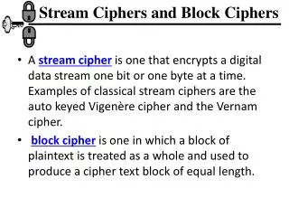
Block vs. stream ciphers M1, M2, …, Mn m1, m2, …, mn Internal state - IS Block cipher K K Stream cipher C1, C2, …, Cn c1, c2, …, cn Ci=fK(Mi) ci = fK(mi, ISi) ISi+1=gK(mi, ISi) Every block of ciphertext is a function of the current block of plaintext and the current internal state of the cipher Every block of ciphertext is a function of only one corresponding blockof plaintext
Typical stream cipher Sender Receiver initialization vector (seed) initialization vector (seed) key key Pseudorandom Key Generator Pseudorandom Key Generator keystream ki keystream ki mi ci ci mi plaintext ciphertext ciphertext plaintext
Electronic CodeBook Mode – ECB Encryption K K K K M3 M1 M2 MN MN-1 K E E E E E . . . C3 C1 C2 CN CN-1 Ci = EK(Mi) for i=1..N
Electronic CodeBook Mode – ECB Decryption K K K K C3 C1 C2 CN CN-1 K D D D D D . . . M3 M1 M2 MN MN-1 Ci = EK(Mi) for i=1..N
Counter Mode - CTR Encryption K K K K IV+N-1 IV+N-2 IV IV+1 IV+2 . . . K E E E E E . . . kN kN-1 k2 k3 k1 mN mN-1 m2 m3 m1 c2 cN-1 c3 cN c1 ci = mi ki ki = EK(IV+i-1) for i=1..N
Counter Mode - CTR Decryption K K K K IV+N-1 IV+N-2 IV IV+1 IV+2 . . . K E E E E E . . . kN kN-1 k2 k3 k1 cN cN-1 c2 c3 c1 m2 mN-1 m3 mN m1 mi = ci ki ki = EK(IV+i-1) for i=1..N
Counter Mode - CTR IV IV counter counter 1 L 1 L IN IN K K E E OUT OUT 1 1 L L ci ci IS1 = IV ci = EK(ISi) mi ISi+1 = ISi+1 mi mi
Cipher Block Chaining Mode - CBC Encryption m3 m1 m2 mN mN-1 . . . IV E E E E E . . . cN c1 cN-1 c2 c3 ci = EK(mi ci-1) for i=1..Nc0=IV
Cipher Block Chaining Mode - CBC Decryption cN c1 cN-1 c2 c3 D D D D D . . . . . . IV m3 m1 m2 mN mN-1 mi = DK(ci) ci-1for i=1..Nc0=IV
Primary factor in choosing the encryption/decryption unit architecture Symmetric-key cipher mode of operation: 1. Non-feedback cipher modes ECB, counter mode 2. Feedback cipher modes CBC, CFB, OFB
Non-feedback Counter Mode - CTR IV+N IV+N-1 IV IV+1 IV+2 . . . E E E E E . . . M2 MN MN-1 M0 M1 C2 CN-1 C3 CN C1 Ci = Mi AES(IV+i) for i=0..N
Feedback cipher modes - CBC M3 M1 M2 MN MN-1 . . . IV E E E E E . . . CN C1 CN-1 C2 C3 C1 = AES(MiIV) Ci = AES(MiCi-1) for i=2..N
Feedback cipher modes CBC, CFB, OFB
k-rounds Loop Unrolling multiplexer register k rounds round 1 round 2 combinational logic . . . . . round k
Loop Unrolling: Timing CLK P2 P1 P3 IN C1 C2 OUT #rounds/k · extended_clock_period
Loop Unrolling: Speed vs. Area speed 1 + speed = speed basic 1 + / k << 1 loop-unrolling basic architecture k=5 k=4 k=3 k=2 area
Architectures suitable for feedback modes MUX register round 1 MUX round 2 combinational logic one round . . . . round K round 1 round 2 . . . . round #rounds
Decreasing area by resource sharing After Before D1 D0 D0 D1 multiplexer F F F D0’ D1’ D1’ D0’ register
Resource Sharing: Speed vs. Area Throughput - basic architecture - resource sharing basic architecture Area resource sharing
Non-Feedback Cipher Modes ECB, counter, OCB
Comparison for non-feedback cipher modes, e.g. Counter Mode - CTR IV+N IV+N-1 IV IV+1 IV+2 . . . E E E E E . . . M2 MN MN-1 M0 M1 C2 CN-1 C3 CN C1 Ci = Mi AES(IV+i) for i=0..N
OCB Control sum MN MN-1 0 M2 IV M1 length g(L) E ZN ZN-1 Z2 Z1 ZN E E E E E . . . L E MN ZN-1 Z2 Z1 bits R CN T CN-1 C2 C1 Zi=f(L, R)
Increasing speed by parallelprocessing Encryption/ decryption unit Encryption/ decryption unit Encryption/ decryption unit Encryption/ decryption unit Encryption/ decryption unit Encryption/ decryption unit
Increasing speed using pipelining Cipher 2 Cipher 1 round 1 round 1 round 2 . . . target clock period, e.g., 20 ns . . . round 10 round 16 block size Speed = target_clock_period
Pipelined operation of the encryption unit clock cycle 8 4 1 2 5 3 6 7 B1 B3 B6 B7 B4 B8 B5 B2 B2 B5 B6 B3 B7 B4 B1 B1 B4 B5 B2 B6 B3 B3 B4 B1 B5 B2 clock cycle 16 12 9 10 13 11 14 15 B10 B11 B14 B15 B12 B16 B9 B13 B9 B10 B13 B14 B11 B15 B8 B12 B8 B9 B12 B13 B10 B14 B7 B11 B7 B8 B11 B12 B9 B13 B6 B10
Full outer-round pipelining #rounds registers round 1 = one pipeline stage round 2 = one pipeline stage . . . . round #rounds = one pipeline stage Total # of pipeline stages = #rounds
Full mixed inner- and outer-round pipelining k registers round 1 = k pipeline stages . . . . round 2 =k pipeline stages . . . . . . . . round #rounds =k pipeline stages . . . . Total # of pipeline stages = #rounds·k
k-stageOuter-Round Pipelining multiplexer register1 pipeline stage 1 = round 1 register2 k rounds pipeline stage 2 = round 2 . . . . register k pipeline stage k = round k
Outer-Round Pipelining: Timing CLK P2 P1 P3 P4 P6 P5 IN C2 C3 C1 C4 OUT #rounds · clock_period
Outer-Round Pipelining: Speed vs. Area speed k=5 outer-round pipelining non-feedback modes k=4 k=3 outer-round pipelining feedback modes k=2 basic architecture area
Outer-round Pipelining K registers MUX register MUX round 1 = one pipeline stage combinational logic one round, no pipelining round 2 = one pipeline stage . . . . round K = one pipeline stage K registers round 1 = one pipeline stage round 2 =one pipeline stage . . . . round #rounds =one pipeline stage
k-stage Inner-Round Pipelining multiplexer register1 pipeline stage 1 register2 one round pipeline stage 2 . . . . register k pipeline stage k
Inner-Round Pipelining: Timing CLK P1 P2 P3 P4 P6 P5 IN C3 C1 C2 C4 OUT #rounds · (k · reduced_clock_period)