Download
1 / 72
740 likes | 756 Views
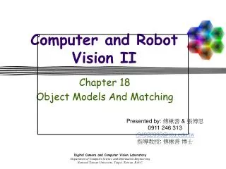
Robot vision review. Martin Jagersand. What is Computer Vision?. Computer Vision. Computer Vision. Computer Graphics. Image Processing. Three Related fields Image Processing: Changes 2D images into other 2D images Computer Graphics: Takes 3D models, renders 2D images

E N D
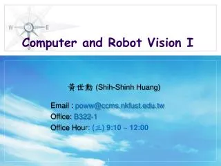
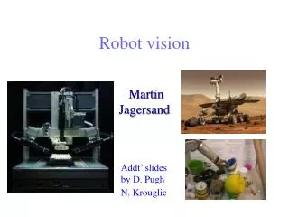
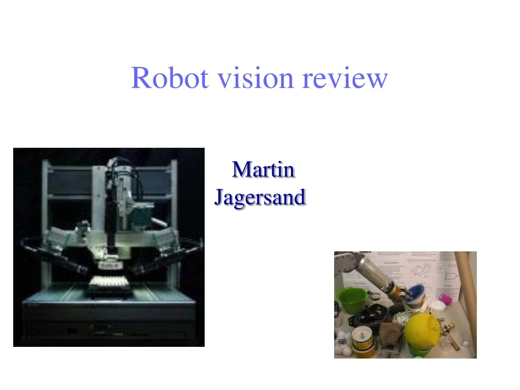
Robot vision review Martin Jagersand
What is Computer Vision? Computer Vision Computer Vision Computer Graphics Image Processing • Three Related fields • Image Processing: Changes 2D images into other 2D images • Computer Graphics: Takes 3D models, renders 2D images • Computer vision: Extracts scene information from 2D images and video • e.g. Geometry, “Where” something is in 3D, • Objects “What” something is” • What information is in a 2D image? • What information do we need for 3D analysis? • CV hard. Only special cases can be solved. 90 horizon
Machine Vision • 3D Camera vision in general environments hard • Machine vision: • Use engineered environment • Use 2D when possible • Special markers/LED • Can buy working system! • Photogrammetry: • Outdoors • 3D surveying using cameras
Vision v u Y X • Full: Human vision • We don’t know how it works in detail • Limited vision: Machines, Robots, “AI” What is the most basic useful information we can get from a camera? • Location of a dot (LED/Marker) [u,v] = f(I) • Segmentation of object pixels All of these are 2D image plane measurements! What is the best camera location? Usually overhead pointing straight down Adjust cam position so pixel [u,v] = s[X,Y]. Pixel coordinates are scaled world coord
Tracking LED special markers v u Y X • Put camera overhead pointing straight down on worktable. • Adjust cam position so pixel [u,v] = s[X,Y]. Pixel coordinates are scaled world coord • Lower brightness so LED brighterest • Put LED on robot end-effector • Detection algorithm: • Threshold brightest pixels I(u,v)>200 • Find centroid [u,v] of max pixels • Variations: • Blinking LED can enhance detection in ambient light. • Different color LED’s can be detected separately from R,G,B color video. Camera LED
Commercial tracking systems Polaris Vicra infra-red system(Northern Digitial Inc.) MicronTracker visible light system (Claron Technology Inc.)
Commercial tracking system Images acquired by the Polaris Vicra infra-red stereo system: right image left image
IMAGE SEGMENTATION • How many “objects” are there in the image below? • Assuming the answer is “4”, what exactly defines an object? Zoom In 11/5/2019 Introduction to Machine Vision
8 BIT GRAYSCALE IMAGE 11/5/2019 Introduction to Machine Vision
GRAY LEVEL THRESHOLDING Objects Set threshold here 11/5/2019 Introduction to Machine Vision
BINARY IMAGE 11/5/2019 Introduction to Machine Vision
CONNECTED COMPONENT LABELING: FIRST PASS A A EQUIVALENCE: B=C A A A B B C C B B B C C B B B B B B 11/5/2019 Introduction to Machine Vision
CONNECTED COMPONENT LABELING: SECOND PASS A A TWO OBJECTS! A A A B B B C C B B B B B C B C B B B B B B 11/5/2019 Introduction to Machine Vision
IMAGE SEGMENTATION – CONNECTED COMPONENT LABELING 4 Neighbor Connectivity 8 Neighbor Connectivity 11/5/2019 Introduction to Machine Vision
What are some examples of form parameters that would be useful in identifying the objects in the image below? 11/5/2019 Introduction to Machine Vision
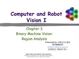
OBJECT RECOGNITION – BLOB ANALYSIS • Examples of form parameters that are invariant with respect to position, orientation, and scale: • Number of holes in the object • Compactness or Complexity: (Perimeter)2/Area • Moment invariants • All of these parameters can be evaluated during contour following. 11/5/2019 Introduction to Machine Vision
GENERALIZED MOMENTS • Shape features or form parameters provide a high level description of objects or regions in an image • For a digital image of size n by m pixels : • For binary images the function f(x,y) takes a value of 1 for pixels belonging to class “object” and “0” for class “background”. 11/5/2019 Introduction to Machine Vision
GENERALIZED MOMENTS X 7 Area 33 20 159 Moment of Inertia 64 93 Y 11/5/2019 Introduction to Machine Vision
SOME USEFUL MOMENTS • The center of mass of a region can be defined in terms of generalized moments as follows: 11/5/2019 Introduction to Machine Vision
SOME USEFUL MOMENTS • The moments of inertia relative to the center of mass can be determined by applying the general form of the parallel axis theorem: 11/5/2019 Introduction to Machine Vision
SOME USEFUL MOMENTS • The principal axis of an object is the axis passing through the center of mass which yields the minimum moment of inertia. • This axis forms an angle θ with respect to the X axis. • The principal axis is useful in robotics for determining the orientation of randomly placed objects. 11/5/2019 Introduction to Machine Vision
Example X Principal Axis Center of Mass Y 11/5/2019 Introduction to Machine Vision
3D MACHINE VISION SYSTEM XY Table Laser Projector Digital Camera Field of View Plane of Laser Light Granite Surface Plate P(x,y,z) 11/5/2019 Introduction to Machine Vision
3D MACHINE VISION SYSTEM 11/5/2019 Introduction to Machine Vision
3D MACHINE VISION SYSTEM 11/5/2019 Introduction to Machine Vision
Dilation 28
Opening erosion followed by dilation, denoted ∘ eliminates protrusions breaks necks smoothes contour 29
Opening 30
Opening 31
Opening 32
Closing dilation followed by erosion, denoted • smooth contour fuse narrow breaks and long thin gulfs eliminate small holes fill gaps in the contour 33
Closing 34
Image Processing Edge detection Filtering: Noise suppresion
Image filtering Mean filter = * Input image f Output image g Filter h
Animation of Convolution To accomplish convolution of the whole image, we just Slide the mask Original Image Mask C4,2 C4,3 C4,4 Image after convolution
Gaussian filter Compute empirically = * Filter h Input image f Output image g
Convolution for Noise Elimination --Noise Elimination The noise is eliminated but the operation causes loss of sharp edge definition. In other words, the image becomes blurred
Convolution with a non-linear mask Median filtering There are many masks used in Noise Elimination Median Maskis a typical one The principle of Median Mask is to mask some sub-image, use the median of the values of the sub-image as its value in new image J=1 2 3 Rank: 23, 47, 64, 65, 72, 90, 120, 187, 209 I=1 2 3 median Masked Original Image
Edge detection using the Sobel operator In practice, it is common to use: Magnitude: Orientation:
Sobel operator Magnitude Orientation Original
Effects of noise on edge detection / derivatives Consider a single row or column of the image Plotting intensity as a function of position gives a signal Where is the edge?
Solution: smooth first Look for peaks in Where is the edge?
Vision-Based Control (Visual Servoing) Initial Image User Desired Image
Vision-Based Control (Visual Servoing) : Current Image Features : Desired Image Features
Vision-Based Control (Visual Servoing) : Current Image Features : Desired Image Features
Vision-Based Control (Visual Servoing) : Current Image Features : Desired Image Features
Vision-Based Control (Visual Servoing) : Current Image Features : Desired Image Features