Download
1 / 22
220 likes | 307 Views
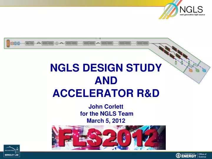
NGLS DESIGN STUDY AND ACCELERATOR R&D John Corlett for the NGLS Team March 5, 2012. Motivation. Coherent X-rays with high repetition rate, unprecedented average brightness, and ultrafast pulses . Today’s storage ring x-ray sources. Weak pulses at high rep rate. ~ nanoseconds.

E N D
NGLS DESIGN STUDYANDACCELERATOR R&D John Corlett for the NGLS TeamMarch 5, 2012
Motivation Coherent X-rays with high repetition rate, unprecedented average brightness, and ultrafast pulses Today’s storage ring x-ray sources Weak pulses at high rep rate ~ nanoseconds ~nanojoule ~ picoseconds Today’s x-ray laser sources ~ milliseconds Intense pulses at low rep rate … … ~ femtoseconds ~millijoule Intense pulses at high rep rate ~ microseconds Tomorrow’s x-ray laser sources ~0.1 millijoule ~ attoseconds to femtoseconds
Approach High average power electron beam distributed to an array of FELs from high rep-rate injector and CW SCRF linac Beam spreader High-brightness, high rep-rate gun and injector CW superconducting linac, laser heater, bunch compressor Array of independent FELs X-ray beamlines and endstations
Capabilities High repetition rate soft X-ray laser array • Up to 106 pulses per second • Average coherent power up to ~100 W Spatially and temporally coherent X-rays (seeded) • Ultrashort pulses from 250 as – 250fs • Narrow energy bandwidth to 50 meV Tunable X-rays • Adjustable photon energy from 280 eV – 1.2 keV • higher energies in the 3rd and 5th harmonics • Polarization control • Moderate to high flux with 108– 1012 photons/pulse Expandable • Capability • Capacity • More photons per unit bandwidth • More photons per second • Shorter pulses • Controlled trade-off between time and energy resolution
Science requirements drive machine design • Tuning range • Maximum photon energy • Peak flux • Average Flux • Repetition rate • Two-color capability • Pulse duration • Bandwidth • Accuracy • Stability • Synchronization • Contrast ratio
Accelerator Systems R&D priorities • High repetition rate • Injector “APEX” • Beam spreader • Advanced FEL operation • Modeling and optimization • Seeding approaches • Seed lasers • Superconducting undulators • Developing partnerships • SCRF • RF power
APEX gun: high-brightness MHz electron source • APEX cavity is successfully RF conditioned
APEX Activity and Plans F. Sannibale Yb fiber photocathode drive laser • 1 MHz reprateYb fiber laser • LLNL/UCB/LBNL collaboration
Photocathode materialsR&D K2CsSb: 6% QEat 532 nm 0.36 microns / mm rmsen >> 1 week lifetime Good lifetime at 10-9 mBar Low transverse momentum High QE
APEX stages • Phase-II: Beam characterization at 15–30 MeV • 6-D brightness measurements Phase I: Beam characterization at gun energy (750 keV) Phase 0: Gun and photocathode tests Diagnostics systems in collaboration with Cornell CLASSSE Accelerating cavities in collaboration with ANL AWA • Planning for final installation in 2013
Optimizing the beam spreader Electrostatic septum Kicker (0.6 mrad – was 3 mrad) Magnetic Septum DC Bends • Electrostatic allows 5x weaker kickers (1/5 stability tolerance) • Footprint reduced ~1/3
Optimizing the beam spreader Electrostatic Septum 2.0 m, 9.6 mrad Magnetic Septum 1 m, 45 mrad Pulsed Kicker 1 m, 0.6 mrad Linac line D D F x ARC D z • Electrostatic allows 5x weaker kickers (1/5 stability tolerance) • Footprint reduced ~1/3
Linac developments – “10/25/11” layout Accelerating cryomodules Linearizer cryomodules Laser heater Injector Spreader CM1 CM2 CM9 CM30 CM3 CM10 HL Bunch compressor 1 Bunch compressor 2 Accelerating cryomodules BC1 168 MeV BC2 640 MeV SPRDR 2.4 GeV GUN 1 MeV Heater 70 MeV ~670 m
Injector optimization Buncher 5 keV Gun • Pareto front of genetic optimization • 300 pC, ~70 MeV design point • Delivers required beam brightness RMS energy spread RMS bunch length (mm) 1 keV Projected normalized emittance (m-rad, 100%)
Beam dynamics modeling through linac Longitudinal beam phase-space at entrance of FEL beamlines* • Two-stage compression • 2.4 GeV • APEX-gun generated beams (300pC) • ≥ 600 A peak current and small residual energy chirp within usable beam core • limited CSR-induced projected emittance growth Twiss functions through the Linac Current profile *’Elegant’ simulation through the linacstarting from an ASTRA-simulated beam out of the APEX-gun based injector
Self-seeded FELs • e- chicane 1st undulator 2ndundulator with taper Single crystal: C(400) SASE FEL Self-seeded FEL Seeded FEL spectrum SASE FEL spectrum Initial results: 40x reduction in BW (40x increase in peak brightness) ~ 0.5 eV Near Fourier Transform limit ~ 20 eV LCLS Soft X-ray Self Seeding – in planning stages
Laser seeded FEL – ”ECHO” • Developing R&D plans • Beam experiments • Laser developments EEHG HHG HGHG
HHG seeded FEL R&D • HHG seeding at ~50–100 eV • HGHG to reach 1.2 keV 1 kHz, 40 mJ, HHG source for seeding R&D
FEL harmonics measurements at LCLS • Now using filters Daniel Ratner • Fit to detected signal level with attenuators • Future using spectroscopic fast CCD detector • LBNL detector
Superconducting undulator R&D • Planar Nb3Sn undulator • HTS tape undulator • Cryostat for test and measurement
Summary • DOE has approved Mission Need for a Next Generation Light Source • LBNL led the effort • We are: • Developing science case and experimental requirements • Evolving machine design to best meet science needs • Executing and developing R&D plans • Strengthening and building collaborations