Download
1 / 15
160 likes | 198 Views
Learn about the benefits of improving system performance, reducing maintenance, and achieving higher efficiency through frameless motor mounting. Understand mechanical considerations, bonding techniques, and recommended adhesives for secure motor installation.

E N D
KollmorgenFrameless Motor Mounting PracticesBonding with Structural AdhesivesApril 2012
Mounting Considerations … • Embedded Motion Technology - Frameless Mounting Considerations • The benefits of Improved System Performance, Reduced Maintenance, Smaller Mechanical Footprint, Higher System Efficiency are understood • Customer still has a key question in mind … • I like the frameless design concept but how do I mount the motor components into my machine?
Mounting Considerations … • Mechanical Mounting Considerations • Customer’s own bearings • Customer’s shafting / drivetrain • Bearing precision and machining tolerances are dependent more on customer machine requirements than frameless motor mounting requirements • Run-out more dependent on customer requirements • Air gap of 0.015” – 0.075” (0.38 mm – 1.9 mm) each side of rotor needed for frameless motor • Mounting; Bonding, Clamping, and Shrink fit options discussed in some detail in the KBM Selection Guide
Radial Running Clearance – “AirGap” Source: KBM Selection Guide p.75 – KM_SG_00073_RevB_EN Source: KBM Selection Guide p.69 – KM_BR_00073_RevA_UK_KBM
KBM-43X03 Mounting Example Bonding Customer Through-bore type Encoder KBM-43X03 Stator Customer Duplex Bearing KBM-43X03 Rotor Customer Machine Shaft Customer Housing
KBM-43X03 Mounting Example Bonding Customer Housing with Stator embedded Customer Shaft with Rotor
KBM-43X03 Mounting Example Bonding Customer Housing KBM Stator Customer Shaft KBM Rotor
KBM-43X03 Mounting Example Bonding Customer Housing Housing / Stator Exploded View KBM Stator
KBM-43X03 Mounting Example Bonding Housing / Stator Assembly See Detail A 3D to 2D
KBM-43X03 Mounting Example Bonding Detail A – Stator / Housing Depth stop shoulder feature 0.10/0.05 mm gap per side, “slip fit” Insert Stator 0.26/0.13 mm additional adhesive groove, 50+% of surface 2 mm min. end turn to housing clearance • Recommended Structural Epoxy 3M Scotchweld 2214 Hysol EA934NA
KBM-43X03 Mounting Example Bonding Recommended for KBM Frame size 118XX and smaller Recommended Structural Epoxy: 3M Scotchweld 2214 Hysol EA934NA Design Recommendations Cylindrical cup shape customer housing Locating shoulder for precise location Lead in chamfer to aid in assembly operation Maintain clearance over potted winding surfaces > 2 mm Slip fit with housing of 0.1-0.2 mm over stator OD max Adhesive grooves with extra slip fit gap of 0.13-0.26 mm Parts will “self-center” during cure by orienting in vertical axis Maximum Cure temperature of 155 C to prevent insulation damage Please Note that: Adhesive manufacture guidelines should be followed Other adhesives can be used Customer ultimately responsible for proper design of: Housing dimensions accounting for thermal effects Proper surface preparation and application of adhesive
KBM-43X03 Mounting Example Bonding Customer Shaft Rotor Rotor / Shaft Exploded View
KBM-43X03 Mounting Example Bonding Rotor / Shaft Assembly 3D to 2D See detail B
KBM-43X03 Mounting Example Bonding • Recommended Retaining Compound: Loc-Tite 640 No adhesive grooves with Retainer Compound mounting configuration Rotor 0.05/0.025 mm gap per side, “precise location slip fit” Bolt-on Mounting also practical for removable rotor Fit depth to shoulder Shaft Detail B – Rotor / Shaft Assembly
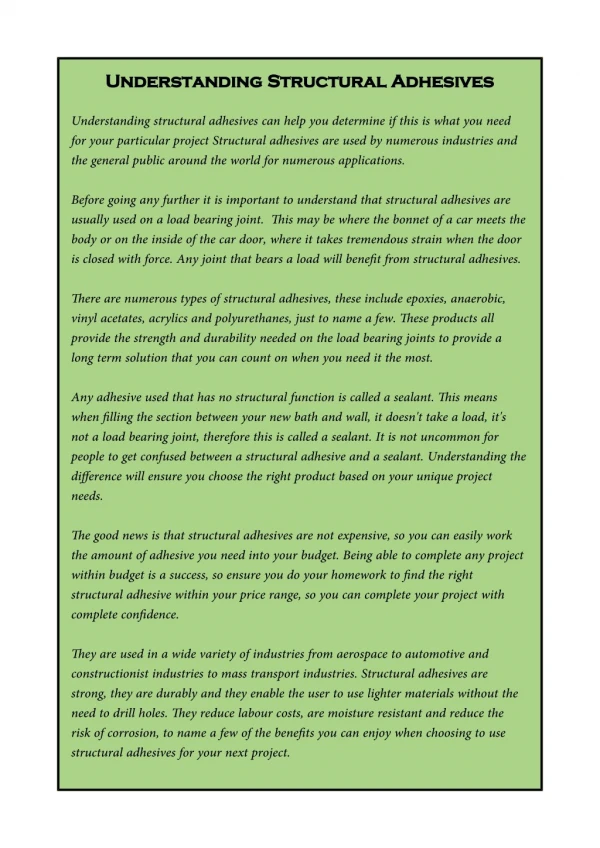
Mounting Considerations … • Bonding with Structural Adhesives • Bearing precision and machining tolerances are dependent more on customer machine requirements than frameless motor mounting requirements • Structural adhesives represent a cost-effective, industry proven, and mechanically sound approach to frameless motor mounting • Several mounting options; Bonding, Clamping, and Shrink fit options are discussed in some detail in the KBM Selection Guide