Download
1 / 38
380 likes | 396 Views
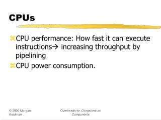
This article discusses the advantages and performance analysis of multi-cycle CPUs compared to single-cycle CPUs. It explores the instruction decoding process and the role of clocks in CPU operations. It also introduces different types of oscillators and their impact on clock stability. The article concludes with a discussion on reducing cycle time and the implementation of multi-cycle CPUs in real-world applications.

E N D
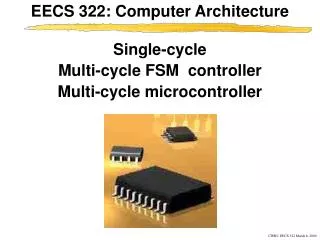
b1101Multi-Cycle CPUs ENGR xD52 Eric VanWyk Fall 2014
Acknowledgements • Mark L. Chang lecture notes for Computer Architecture (Olin ENGR3410) • Microchip Technology Inc (Datasheet) • A. Sahu, Indian Institute of Technology
Today • Clocks • Recall Single-Cycle CPUs • Single-Cycle Shortcomings • Multi-Cycle CPUs • Instruction Decoding with an FSM
Instruction Fetch Instruction Decode Operand Fetch Execute Result Store Next Instruction Execution Overview • Fetch instruction from memory • Decode instruction into actions/controls • Fetch/Decode operands • Compute result value or status • Push result(s) to storage • Determine next instruction
Instruction Fetch Instruction Decode Operand Fetch Execute Result Store Next Instruction Execution Overview • Fetch instruction from memory • Decode instruction into actions/controls • Fetch/Decode operands • Compute result value or status • Push result(s) to storage • Determine next instruction • Reference Lecture b100x
Clocks and Stability • The clock is a massive, chip wide signal • All timing slaves to it • Huge buffers to keep everyone in line • Usually a Crystal (XTAL / XO) as a time base • Very precise – Easily tens of parts per million • Sometimes an RC oscilator • ModCon all over again
Types of Oscillators w/ DigiKey Pricing • Crystals: • 50ppm 16 cents @ 1kU • 10ppm 24 cents (for common frequencies) • XO (Crystal + Support Circuitry) • 50ppm 53 cents • 10ppm 84 cents • 0.5ppm $1.12 • TCXO (Temperature Compensated X0) • 0.5ppm $1.20 • 280ppb $10.41 • OCXO (Oven Compensated XO) • 50ppb $39 • 5ppb $112 • 0.1ppb $1,798
Clocks and Instability • Specialized systems can change clock freq • Phase Locked Loop to multiply / divide freq • Some can change this multiplier during operation • Spread Spectrum Oscillator: http://www.mecxtal.com/clk_hm.php
Clocks Change Slowly • Spread Spectrum effects are slow! • How many clock cycles is 0.01ms? http://www.minicircuits.com/app/VCO15-20.pdf
Clock Changes Slower than Instructions • For our processors, clock isn’t adjustable • Decided at Manufacture Time • For modern processors, clock adjusts: • Very explicitly. Processor pauses during change. • Dynamic Frequency Scaling Power Save • Ben has been working on changing this
Information Rippling • Each Clock Cycle “ripples” left to right • Elements emit garbage values until they stabilize • Elements on the leading edge of cycle (LEFT) • Spend most of the time “bored” (stable) • Under-utilized • Elements on the lagging edge of cycle (RIGHT) • Spend most of the time twitching as things settle • Spend unnecessary dynamic power
PC Instr. Memory Reg Read mux ALU Adder mux PCsetup PC Instr. Memory Reg Read mux ALU Data Memory PC Instr. Memory Reg Read mux ALU mux Reg Setup PC Instr. Memory mux PCsetup PC Instr. Memory Reg Read mux ALU Data Memory mux Reg Setup Performance of Single-Cycle Machine Clock speed is set by the slowest instruction Arithmetic & Logic Load Store Branch Jump
Clock TL;DR; • Unable to change for each instruction • Slow instruction slows EVERY instruction • Harrison Bergeron applied to Transistors
storage element storage element Acyclic Combinational Logic (A) Acyclic Combinational Logic storage element Acyclic Combinational Logic (B) storage element storage element Reducing Cycle Time • Cut combinational dependency graph and insert register / latch • Do same work in N fast cycles, rather than one slow one
Goals • Free up fast instructions from slow clock curse • Load Word is Super Slow • Make better use of available resources • Reuse components (2 Memories, 2 or 3 Adders) • Free up space to speed up components • One big fast ALU, not multiple slow ALU/adders
Multi-Cycle CPUs in the Wild • Common in small embedded spaces • PIC16, PIC18 • 4 bit micros (watches) • Marketing will try to confuse you • Advertise MHz • Hide CPI, Instructions per second, etc http://ww1.microchip.com/downloads/en/DeviceDoc/41213D.pdf
Preview of White Boards to Come • We will go to the white boards “soon”. • You will create the schematic necessary to run the RTL design I’m about to give you. • I’m “cheating” and giving you parts of MY answer, to make your reinvention smoother • There is nothing sacred about MY answer, • You’re usually on the hook for the whole shebang • If it fulfils the contract and is small/fast, awesome.
Strategy • Enumerate all the stuff we have to do • Per Instruction • Highlight Common Features • Break tasks in to N phases • N is different for different instructions • Balance work done in each phase
“Typical” Phases • IF: Instruction Fetch • ID: Instruction Decode (& register fetch) • EX: Execute • MEM: Read from Memory • WB: Write Back to Memory • Other Architectures make different divisions!
New Registers IR • Instruction Register (IR) • Instruction fetched from Data Memory • Data Register (MDR) • Data fetched from Data Memory • Operands (A, B) • Fetched from Register File • Result (Res) • Result of the ALU calculation • Some of these may need write enable controls! Rs Rt Rd Imm16 MDR A B ALU RES
Concatenate Aw Aa Ab Da Dw Db Register WrEn File SignExtnd PC WrEnAddr Din Dout Data Memory Old Friends
Phases: Load Word • IF: Instruction Register = Memory[PC] PC=PC+4 • ID: A = RegFile[rs] B = RegFile[IR[16:20]] • EX: Result = A + sign extended immediate • MEM: DataReg = Mem[Result] • WB: RegFile[rt] = DataReg
Phases: ADD • IF: Instruction Register = Memory[PC] PC=PC+4 • ID: A = RegFile[rs] B = RegFile[rt] • EX: Result = A + B • MEM: • WB: RegFile[rd] = Result
Phases: Store Word • IF: Instruction Register = Memory[PC] PC=PC+4 • ID: A = RegFile[rs] B = RegFile[rt] • EX: Result = A + sign extended immediate • MEM: Mem[Result] = B • WB:
Phases: Branch if Equal • IF: Instruction Register = Memory[PC] PC=PC+4 • ID: A = RegFile[rs] B = RegFile[rt] Res = PC + sign extended immediate • EX: if(A==B) PC = Res • MEM: • WB:
Phases: Jump • IF: Instruction Register = Memory[PC] PC=PC+4 • ID: PC = PC[31:28],IR[25:0],b00 • EX: • MEM: • WB:
Lets Make It • Create a Multi-Cycle CPU that can do the instructions on prior pages • Jump, Branch, R-type, I-type, LW, SW • Show everything except the actual decode logic • Reference Lecture b1001, but put everything on one “page” • Sketch a Schematic for your Multi Cycle CPU • ALU, Register File, Unified Instruction/Data Memory • Sign Extender, (Optional) Shift by Two • IR, DR, A, B, Res Registers • OMG MUXES EVERYWHERE • Create a control chart (to show the actual decode logic) • Show each cycle of each instruction • Mux selects, ALU Control Lines, Register Enables • Use “X” for “Don’t Care” • Create a One Hot FSM to generate control signals • Flow Diagram First, then push to DFF and Logic • Then do the ALUsrcB control signal in its entirety • Then the other control signals as time allows • Send to CompArch14@gmail.com “[MultiCycle] Names”
This Page Intentionally Left Blank • Except for that text up there • And some more over here • But really, it is so you don’t accidentally see one possible answer. • But… if you are stuck, go for it.
IR Rs Rt Rd Imm16 WrEn Addr Dout Memory Din Aw Ab Aa Da Registers Dw WrEn Db SignExtnd PC <<2 MDR ALU RES B A Multi Cycle w/ Controls PCSrc MemIn ALUOp ALUSrcA PC_WE IR_WE Mem_WE Concat 4 A_WE B_WE Dst ALUSrcB Reg_WE RegIn
Preview of things to Come • How to control a Multi-Cycle CPU • Timing Concerns and Explicit Balancing • Modern CPUs: Pipelining
Desk Work • Time your Multicycle design from Monday • Do symbolically first, then substitute real numbers • Remember parallel paths!
Summary • Split Single Cycle in to multiple cycles • Use variable number of cycles per instruction • No More Harrison Bergeron-ing • Most Instructions become Faster • Longest Instruction gets Longer • From unbalanced phases • Costs: Registers, control logic