Download
1 / 29
290 likes | 308 Views
Explore a camera-based calibration approach for wide-FOV projectors to correct display surface geometries and lens distortions. Learn about a new pixel shader and GPU mapping techniques achieving accurate projection results. Embrace this technology for immersive visual experiences.

E N D
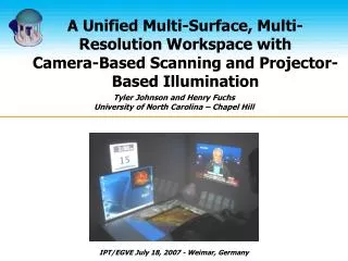
A Personal Surround Environment:Projective Display with Correction forDisplay Surface Geometry and Extreme Lens Distortion Tyler Johnson, Florian Gyarfas, Rick Skarbez, Herman Towles and Henry Fuchs Department of Computer Science University of North Carolina at Chapel Hill IEEE VR– March 14, 2007
Wide-FOV Projectors • Conventional vs. fisheye lens projector Conventional Projector Fisheye-Lens Projector
Outline • Distortion due to Non-Planar Surfaces • Lens Distortion Correction for Projectors • Results • Contributions and Future Work
P Non-planar Display Surfaces
Projector Image Geometry Compensationvia Ray Tracing • Required Information • Viewer location • Display surface model • Projector calibration Display Surface Projector Viewer
Pass 1: Render application scene Pass 2: Remap Pass-1 Image Classic Remapping Algorithm2-Pass Rendering (Raskar ’98) Projector Viewer
Display Surface Geometry Pinhole Projection Pinhole Projection P Pass-1 Pass-2 2-Pass Rendering Assumes no lens distortion!
Distortion with Wide-FOV Lenses Input Image Projected Result
Previous Applications ofWide-FOV Projection • Elumens VisionStation • Hemispherical display screen with fisheye-lens projector for immersive display. • Static projector/display surface relationship. • Distortion correction based on optical/mechanical design specifications.
Previous Applications ofWide-FOV Projection • Konieczny ’05, “A Handheld Flexible Display System” • Allows exploration of volume data using a deformable hand-held screen. • Dynamic display surface.
Our Goals • Our goals were to provide • camera-based calibration for wide-FOV projectors • geometric correction for arbitrary display surfaces • support for tracked viewers
Display Surface Geometry Lens Distortion Correction Pinhole Projection Pinhole Projection Pass-1 Pass-2 Pass-3 3-Pass Rendering
3-Pass Rendering Issuesfor Wide-FOV Lenses • Fisheye lenses are highly non-linear • Pinhole approximation in Pass-2 leads to sampling issues during lens distortion correction in Pass-3.
Sampling Artifacts Display Surface P 3-Pass Rendering All Passes at Projector Resolution (1024 x 768)
Under-sampled! Over-sampled! Over-sampled! Pass-3 Sampling Issues • Fisheye and pinhole lenses have very different spatial sampling characteristics • Leads to sampling issues during lens distortion correction. Pinhole lens (input) Fisheye lens (output)
Sampling Artifact Reduction Display Surface P Pass 1-2: 4x Projector Resolution (4096x3072) Pass 3: (1024x768)
A New Approach • Remove the pinhole approximation of the wide-FOV lens. • Use the actual lens model of the projector. • Allows simultaneous compensation for lens distortion and non-planar surface geometry.
Projector Lens Model Display Surface Geometry Lens Distortion Correction Pinhole Projection Pinhole Projection Pass-1 Pass-2 Pass-3 Changes to Correction Pipeline Use actual projector lens model to avoid resampling artifacts!
Display Surface Projector Image Projector A New Approach Pre-compute where projector rays intersect the display surface! Viewer
Implementation • Pre-compute the projector to display surface (ray) mapping • Store this projector-resolution, 2D to 3D map on GPU as a floating-point texture. • Static map - independent of viewer location. • New Pixel Shader • At each projector pixel: • Look up <x,y,z> vertex on the display surface. • Project the vertex into ideal image to obtain output color.
Results Display Surface P All Passes at Projector Resolution (1024x768)
Calibration • Capture structured light patterns with camera-pair • Calibrate projector • Linear calibration followed by non-linear optimization incorporating projector lens model • Reconstruct surface geometry • RANSAC-based plane fitting technique [Quirk, EDT 06] • General reconstruction techniques can also be used
Pass-1 Viewer Tracking • Could apply simple 2D-2D mapping • Applies only to stationary viewer! • Our approach is independent of the viewer location • Viewer location can be updated each frame 2D - Mapping Only applicable for Stationary Viewer Combined Pass-2 & -3 Remapping
Heterogeneous 2-Projector Display • Also applicable to conventional projectors Display Surface Fisheye-lens Projector Hybrid Display with Conventional and Fisheye-lens Projectors Conventional Projector
Results • Video
Contributions • Single-pass geometric remapping algorithm • Correcting for both extreme lens distortion and display surface geometry • Minimizes sampling and FOV issues with fisheye lenses • Simple GPU shader program implementation • Static 2D:3D mapping stored as 3D floating point texture • Demonstrated applicability • Personal surround environment with a single fisheye lens projector • Conventional or Wide-FOV fisheye AND Heterogeneous displays • Applicable to real-time VR applications with user-head tracking
Future Work • Methods to further reduce sampling artifacts • Mip-mapped Pass-1 textures for geometry optimized sampling. • Application of more general lens models • [Kannala, IEEE TPAMI, Aug. 06] • Real-time, continuous calibration • Accommodate projector or display surface changes while the application running. • Dynamic vs. static Pass-2 re-map function.
Thank You • Funding support: ONR N00014-03-1-0589 • DARWARS Training Superiority program • VIRTE – Virtual Technologies and Environments program • Elumenati LLC for loan of fisheye-lens projector