Download
1 / 7
70 likes | 119 Views
Explore the structural aspects of the Washington Monument to understand how it bears its weight and wind loads efficiently through geometric and load modeling while ensuring safety. Discover internal forces, stresses, and the balance between safety and efficiency for this iconic structure.

E N D
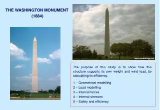
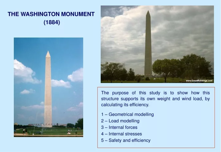
THE WASHINGTON MONUMENT (1884) The purpose of this study is to show how this structure supports its own weight and wind load, by calculating its efficiency. 1 – Geometrical modelling 2 – Load modelling 3 – Internal forces 4 – Internal stresses 5 – Safety and efficiency
1 – GEOMETRICAL MODELLING 2 – LOAD MODELLING 2.1 – Dead loads unit weight of the stone : 23.6 kN/m3 incorporated machinery : 58 kN /m (stairs + elevator) weight of the cap : 2670 kN 2.2 – Live loads : wind The wind is assumed to act horizontally all along one side
Distribution of the critical wind speed along the height Wind pressure on the W.M. : Load modelling ( Bernoulli’s flow law ) Calculations give a nearly constant wind force by unit of height : q = 32 kN/m
3 – INTERNAL FORCES The maximal stresses are in the section x = 0
4 – INTERNAL STRESSES 4.1 NORMAL STRESSES Cross-section at the base (x=0) 4.1 SHEAR STRESSES If we assume max = 5 av , which is exagerated, we find a low value (105 kN/m2) compared with normal stresses (1790 kN/m2). Shear stresses can be neglected.
5 – SAFETY AND EFFICIENCY 5.2 TENSION The structure is made of stone blocks which can not resist tension stresses. stresses or forces would induce failure safety factor = actual stresses or forces 5.1 CRUSHING Wind force which would cause failure : The maximum compressive stress that the stones used can support is 20000 kN/m2 Wind speed which would cause failure :
5.3 - OVERTURNING Extreme winds could tip the W.M. over. 5.4 - CONCLUSION The W.M is safe but not efficient regarding as well the dead loads than the wind forces. Maximum winds recorded in the region (60 m/s) have almost no influence on the dimension of the structure.