Download
1 / 10
100 likes | 222 Views
High Speed Analog Serialization EECS 713. Michael Blecha. Outline. Applications Analog to Digital Converters (ADCs) Low Voltage Differential Signaling (LVDS) Project Deliverables. Application Examples. Oscilloscope Front End Modern oscilloscopes have digital front ends

E N D
High Speed Analog SerializationEECS 713 Michael Blecha
Outline • Applications • Analog to Digital Converters (ADCs) • Low Voltage Differential Signaling (LVDS) • Project Deliverables
Application Examples • Oscilloscope Front End • Modern oscilloscopes have digital front ends • Analog information is digitized and sent to processing/display module • Radio Front End • RF signal is mixed down to baseband and digitized • Most modern radios use digital demodulation • Sensor networks • “Real world” information is analog • Most control loops and decision making processes occur in the digital domain
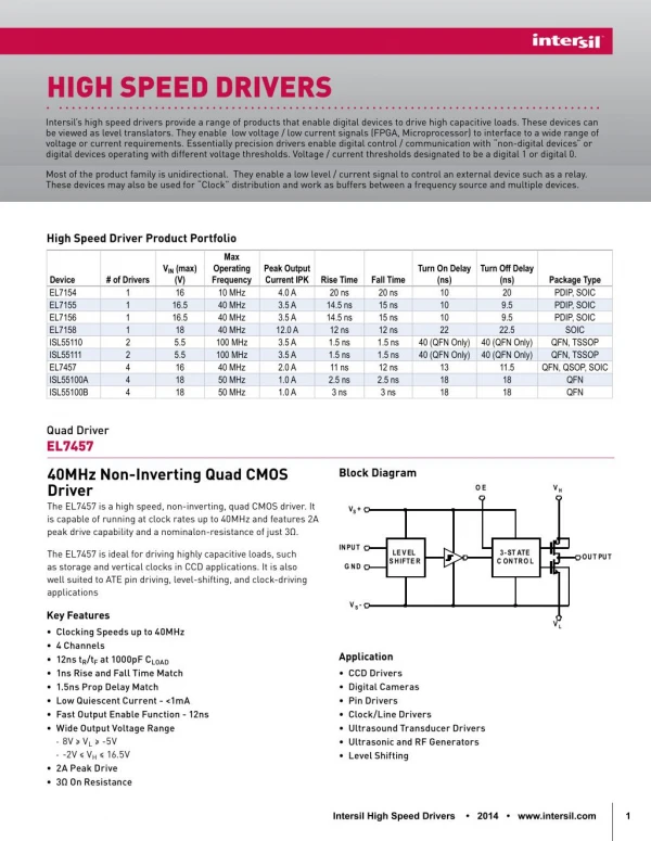
ADCs • Characteristics • Resolution: low (8 bit) to high (16 bit,24 bit +) • Sampling rate: 10s of kSPS to 100s of MSPS • Bandwidth: frequency range that can be sampled • Signal to noise ratio: Ratio of signal to noise introduced • Channels: number of simultaneous parallel data acquisitions • Resolution vs. sampling rate tradeoff • DSPS have finite processing power • Interface has finite bandwidth • DSP may be optimized for certain word sizes (8, 16, 24 bit)
ADC PCB Guidelines • Standard high speed digital design practices remain critical • Ground split • Often helpful, sometimes detrimental if done incorrectly • Star ground often used, connecting analog and digital grounds at single point • Analog and digital portions of ADCs often have different ground return paths (usually different ground pins/balls/pads) • Goal is to have digital return path far from analog section • Power split • Use separate supplies for analog and digital portions • Split power plane and connect with inductors or ferrite beads
LVDS • Serial data transmission interface • Point-point interconnections most common, but multi point fly-by topologies are possible • Low voltage: about 350mV peak to peak • Differential: differential signals terminated with 100 Ω load • Low susceptibility to noise because common mode noise is ignored • Low radiated emissions because opposite currents cancel magnetic fields • Low power consumption
LVDS Use Cases • PCB interconnect • Can connect components 10s of centimeters apart • Some I.C.s have built in terminations, others require external 100 Ω differential termination • Generally implemented as a pair of closely coupled50 Ω single ended striplines or microstrips • Twisted pair • Up to meters in length • Higher speeds need more tightly specified cables (similar to Cat5 vs. Ca6 Ethernet cables) • Commonly used by video display standards (ex: FPD-Link)
LVDS Standards • Standardized by ANSI 644 • Up to 1.9GBit/sec • Zo= 90Ω - 132 Ω • 1.2V common mode • 250mV-450mV transmitted differential voltage • 100mV differential sensitivity at receivers
Project Deliverables • Background information • ADCs • LVDS • High resolution serializer design • 16 bit ADC at 50-100MSPS • LVDS serializer to export data to external DSP • Using separate ADC and serializer to perform timing analysis and determine timing interdependencies of ADC, LVDS driver, and clocking
References • http://www.ti.com/lit/an/slla038b/slla038b.pdf • http://www.analog.com/static/imported-files/application_notes/5957542118600205599850975382134073431740717454123180480718AN586.pdf • http://www.analog.com/static/imported-files/application_notes/AN-1142.pdf • http://www.analog.com/static/imported-files/application_notes/AN-1177.pdf