Download
1 / 55
550 likes | 749 Views
Planning and Cabling. CCNA Exploration Semester 1 Chapter 10. Lesson Objectives. Identify media for a LAN. Identify cables, connections and standards for a LAN. Compare straight through and crossover UTP cables Identify cables, connections and standards for a WAN.

E N D
Planning and Cabling CCNA Exploration Semester 1 Chapter 10
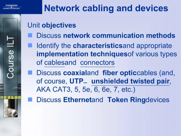
Lesson Objectives • Identify media for a LAN. • Identify cables, connections and standards for a LAN. • Compare straight through and crossover UTP cables • Identify cables, connections and standards for a WAN. • Design an addressing scheme for an internetwork. • Compare and contrast network designs. M Rajab - 2008
Within a LAN • Hubs and switches link hosts M Rajab - 2008
Between networks • Routers link networks together and act as gateways between them. M Rajab - 2008
Hub • Frame comes in. Hub regenerates it and forwards it through all ports except incoming port. • Shared medium, shared bandwidth. Hosts are in the same collision domain. • Cheap. • For small LANs only. M Rajab - 2008
Switch • Frame comes in. Switch regenerates it and forwards it to destination only. • Segments network into separate collision domains. • More expensive but better performance than hub M Rajab - 2008
Arranging switches Star for small networks Extended Star for larger networks, perhaps on several floors Mesh to give redundancy – fault tolerance. M Rajab - 2008
Choice of switch ports • 10 Mbps? • 100 Mbps? • 10/100 Mbps? • 1Gbps? • UTP or fibre optic? • Allow for growth. • Modular switch? • What have our switches got? M Rajab - 2008
Choice of router • Expandability – will you want to add extra modules? • Media – serial ports, Ethernet ports, UTP or fibre optic, how many of each? • Operating System Features – what do you want the router to do? Will you have enough memory to upgrade the operating system? • What ports have our routers got? M Rajab - 2008
Router interfaces M Rajab - 2008
Device Selection FactorsCase 1 M Rajab - 2008
Device Selection FactorsCase 2 M Rajab - 2008
Device Selection FactorsCase 3 M Rajab - 2008
Device Selection FactorsCase 4 M Rajab - 2008
Device Interconnections Making a LAN Connection M Rajab - 2008
Device Interconnections 1 -> 2 Backbone Cabling 1 2 3 3-> 2 Backbone Cabling M Rajab - 2008
Work Area 1 -> 2 Backbone Cabling (Also Know as Vertical Cabling) Telecommunication Room to other Telecommunications room is known as Vertical Cabling Work Area -> Telecommunications Room is known as Horizontal Cabling also known as Distribution cabling Work Area 3-> 2 Backbone Cabling M Rajab - 2008
Horizontal and vertical cable M Rajab - 2008
Total length of cable allowed for UTP connection? Distance to allow between host and switch or hub? Distribution facility or Telecommunications room Horizontal cable Length? Wall socket Patch panel Patch cable Patch cable Length? Length? Switch Host M Rajab - 2008
Total length of cable allowed for UTP connection? 100 metres Distance to allow between host and switch or hub? 50 metres (cable runs are not straight) Distribution facility or Telecommunications room Horizontal cable 90 metres Wall socket Patch panel Patch cable Patch cable 5 metres 5 metres Switch Host M Rajab - 2008
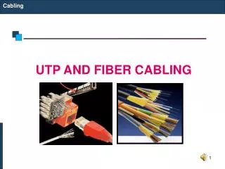
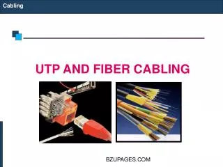
Type of cable used in LAN? • Length: UTP up to 100m, fibre optic longer • UTP inside building. Fibre optic in or out. • Cost: UTP cheaper than fibre optic • Bandwidth: is it enough to meet requirements? • Ease of installation: UTP is easier. • EMI/RFI noise: may need fibre optic. • High capacity link: may need fibre optic. M Rajab - 2008
Attenuation • As a signal propagates (travels) it becomes weaker. This is attenuation • If a signal becomes too weak then the receiving host cannot tell if it is meant to be a 0 or a 1. • This limits cable length. M Rajab - 2008
1 Transmit Transmit 2 3 Receive Receive 6 Correct cable type in LAN • Transmit needs to connect to receive • The crossing over can happen in the cable or inside a device. M Rajab - 2008
Switches and hubs have ports that manage the cross over inside PCs and routers have ports where there is no crossover inside Where is the cross over? • Straight through cable needed if you link a device in one group to a device in the other group • Crossover cable needed if you link devices in the same group M Rajab - 2008
Where is the cross over M Rajab - 2008
Making WAN connection V35 cable or EIA/TIA-232 EIA/TIA-449 X21, V24, HSSI Supplier’s network Supplier’s device on customer’s premisesprovides clocking Customer’s router M Rajab - 2008
Simulating WAN in the lab M Rajab - 2008
Split network into subnets • To cut down the number of broadcasts. Splitting the network into subnets also splits it into separate broadcast domains. • To provide different facilities for different groups of users. • For security. Traffic between subnets can be controlled. M Rajab - 2008
Addressing the network(s) 1 • Start with a topology diagram. • All on one network, or will it be split into subnets? • How many subnets? • How many network bits do we need? • n bits can provide 2n addresses • How many bits are left for hosts? M Rajab - 2008
Addressing the network(s) 2 On each subnet, count the number of: • Router interfaces • Switches • Servers • Admin workstations • General workstations • Printers • IP phones M Rajab - 2008
Addressing the network(s) 2 • How many host bits do we need? • n bits can provide 2n addresses • One for network, one for broadcast • So 2n – 2 host addresses. • 2n – 2 could be 2, 6, 14, 30, 62, 126, 254, 510, 1022, 2046 and so on. • Go for a number big enough to give us enough addresses. M Rajab - 2008
How many subnets? Include point to point links. M Rajab - 2008
Bits to borrow • n bits borrowed for subnetting gives you 2n subnets. • So 1 bit gives 2 subnets, 2 bits give 4 subnets, 3 bits give 8 subnets and so on. • If you need 5 subnets, how many bits do you borrow? • If you need 10 subnets, how many bits do you borrow? 3 4 M Rajab - 2008
Addressing example • The example given in the curriculum shows subnetting without VLSM using 172.16.0.0/22. (172.16.0.0 – 172.16.3.255) • They produce 4 subnets each with 510 addresses. • This is impossible. It will be corrected. • You can do it if you start with 172.16.0.0/21 (172.16.0.0 – 172.16.7.255) M Rajab - 2008
Addressing example no VLSM 172.16.0.0/21 M Rajab - 2008
What we have and need • Given IP address 172.16.0.0/21 • That’s 172.16.0.0 to 172.16.7.255 • 4 subnets needed: • Student LAN has 481 hosts • Instructor LAN has 69 hosts • Administrator LAN has 23 hosts • WAN has 2 hosts M Rajab - 2008
Without VLSM – same size subnets • Biggest subnet has 481 hosts. • Formula for hosts is 2n – 2 • n = 9 gives 510 hosts (n = 8 gives only 254) • So 9 host bits needed. • That means 32 – 9 = 23 network bits • /23 or subnet mask 255.255.254.0 M Rajab - 2008
Network addresses • /23 so subnet mask in binary is • 11111111 11111111 11111110.00000000 • Octet 3 is the interesting one. • Value of last network bit in octet 3 is 2 • So network numbers go up in 2s • 172.16.0.0 • 172.16.2.0 • 172.16.4.0 • 172.16.6.0 M Rajab - 2008
Subnet with no VLSM M Rajab - 2008
Addressing example with VLSM 172.16.0.0/22 is OK M Rajab - 2008
What we have and need • Given IP address 172.16.0.0/22 • That’s 172.16.0.0 to 172.16.3.255 • 4 subnets needed: • Student LAN has 481 hosts • Instructor LAN has 69 hosts • Administrator LAN has 23 hosts • WAN has 2 hosts M Rajab - 2008
With VLSM • Student subnet has 481 hosts. • Formula for hosts is 2n – 2 • n = 9 gives 510 hosts (n = 8 gives only 254) • So 9 host bits needed. • That means 32 – 9 = 23 network bits • /23 or subnet mask 255.255.254.0 • Network address 172.16.0.0 • Broadcast address 172.16.1.255 M Rajab - 2008
With VLSM • Instructor subnet has 69 hosts. • Formula for hosts is 2n – 2 • n = 7 gives 126 hosts (n = 6 gives only 62) • So 7 host bits needed. • That means 32 – 7 = 25 network bits • /25 or subnet mask 255.255.255.128 • Network address 172.16.2.0 • Broadcast address 172.16.2.127 M Rajab - 2008
With VLSM • Admin subnet has 23 hosts. • Formula for hosts is 2n – 2 • n = 5 gives 30 hosts (n = 4 gives only 14) • So 5 host bits needed. • That means 32 – 5 = 27 network bits • /27 or subnet mask 255.255.255.224 • Network address 172.16.2.128 • Broadcast address 172.16.2.159 M Rajab - 2008
With VLSM • WAN subnet has 2 hosts. • Formula for hosts is 2n – 2 • n = 2 gives 2 hosts • So 2 host bits needed. • That means 32 – 2 = 30 network bits • /30 or subnet mask 255.255.255.252 • Network address 172.16.2.160 • Broadcast address 172.16.2.163 M Rajab - 2008
Visually with VLSM 172.16.0.0 172.16.1.0 172.16.2.0 172.16.3.0 Instructor Student Admin WAN M Rajab - 2008
Case 2. Given 192.168.1.0/24 M Rajab - 2008
Subnet 192.168.1.0/24 • 2 subnets with 28 hosts each (largest) • 5 host bits 25 - 2 = 30 would be just enough • But allow for expansion: 6 host bits give 62 • Network bits 32 - 6 = 26 • so /26 or subnet mask 255.255.255.192 M Rajab - 2008
Subnet 192.168.1.1/24 • 1 subnets with 14 hosts • 4 host bits 24 - 2 = 14 would be just enough • But allow for expansion: 5 host bits give 30 • Network bits 32 - 5 = 27 • so /27 or subnet mask 255.255.255.224 • 0-127 range already used M Rajab - 2008