Download
1 / 16
200 likes | 470 Views
FIGURE 10.1 Effect of Humidity on Temperature in Autoclave. The top curve shows that only when all the air is removed that 121 C can be achieved at 100 kPa (15 lb/in 2 ). Even when 50% of air is removed it still requires 150 kPa (23 lb/in 2 ) to reach 121 C. (Data from Breach, 1968.). ◦. ◦.

E N D
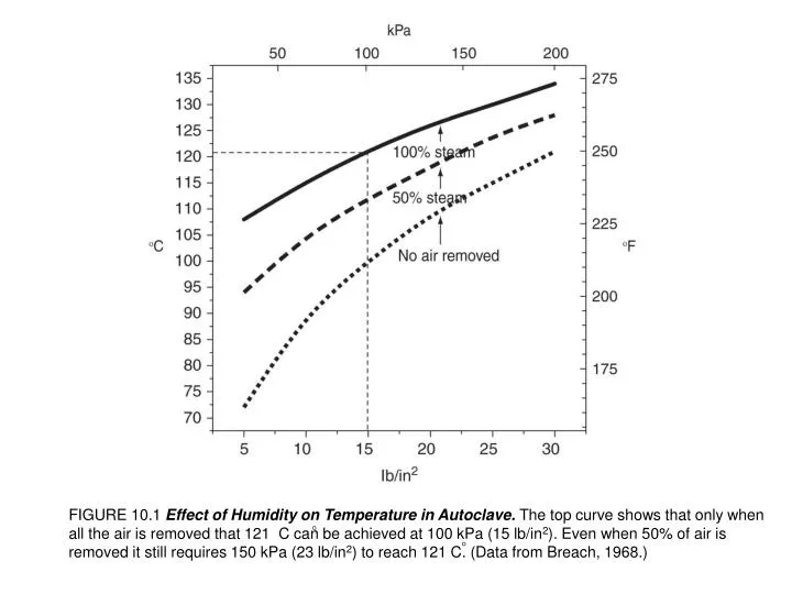
FIGURE 10.1 Effect of Humidity on Temperature in Autoclave. The top curve shows that only when all the air is removed that 121 C can be achieved at 100 kPa (15 lb/in2). Even when 50% of air is removed it still requires 150 kPa (23 lb/in2) to reach 121 C. (Data from Breach, 1968.) ◦ ◦
◦ FIGURE 10.2 Washing and Sterilizing Glassware. Sterilization conditions: autoclave at 121 C for 15 min; oven, minimum of 160 C for 1 h (see Protocol 10.1). Caps are sterilized separately from bottles to avoid condensation forming in bottles if autoclaved with caps in place (see Fig. 10.3). ◦
FIGURE 10.3 Sterilizing Capped Bottles. These bottles were autoclaved with Thermalog sterility indicators inside. Thermalog turns blue with high temperature and steam, and the blue area moves along the strip with time at the required sterilization conditions. The cap on the leftmost bottle was tight, and each succeeding cap was gradually slacker, until finally no cap was used on the bottle farthest to the right. The farthest left bottle is not sterile because no steam entered it. The second bottle is not sterile either, because the liner drew back onto the neck and sealed it. The next three bottles are all sterile, but the brown stain on the indicator shows that there was fluid in them at the end of the cycle. Only the bottle at the far right is sterile and dry. The glass indicators (Browne’s tubes) all implied that their respective bottles were sterile. (See also Plate 22a.)
FIGURE 10.4 Siphon Pipette Washer. Connected to main water supply. A slow fill establishes a siphoning action and drains the main chamber, which then refills. This process is repeated many times over 4 to 6 h. The pipettes shown here are as collected from use. Before the pipette basket is placed in the washer, the plugs areblown out and the pipettes inverted, as in Fig. 10.5.
FIGURE 10.5 Washing and Sterilizing Pipettes. Plugs are removed by compressed air (top left) and the pipettes are washed by automatically repeated emptying and filling of the pipette washer before transferring to a drier (top right). Plugs are reinserted (bottom right; see also Fig. 10.6) and the pipettes are placed in cans, sealed with sterile-indicating tape or marker and sterilized by hot air for a minimum of 1 h (see also Fig. 10.7).
FIGURE 10.6 Semiautomatic Pipette Plugger (Bellco). (a) Pipette plugger (Bellco) with front cover lifted (front cover should always be down in operation). (b) A strand of cotton is fed through the loading aperture, the appropriate length is inserted in the end of the pipette, and a section is cut off (photo taken on older model). Different thicknesses of cotton are required for different sizes of pipette.
FIGURE 10.7 Sterilizing Oven. Pipette cans are stacked with spaces between to allow circulation of hot air. Brown staining on front of oven shows evidence of volatile material from sterile-indicating tape, a problem when using tape in a hot oven.
FIGURE 10.8 Packaging Screw Caps for Sterilization. The caps are enclosed in a glass Petri dish, which is then sealed in an autoclavable nylon bag.
FIGURE 10.9 Water Purification. Tap water is fed to a storage container via reverse osmosis or glass distillation. This semipurified water is then recycled back to the storage container via carbon filtration, deionization, and micropore filtration. Reagent-quality water is available at all times from the storage reservoir; media-quality water is available from the micropore filter supply (at right of diagram). If the apparatus recycles continuously, then water of the highest purity will be collected first thing in the morning for the preparation of medium (see also Fig. 4.15).
FIGURE 10.10 Sterile Filtration. (a) In-line filter. Nonsterile medium from peristaltic pump (see Fig. 10.12) or pressure vessel (see Fig. 10.13). (b) Bottle-top filter or filter flask (designs are similar) for connection to vacuum pump. Medium added to upper chamber and collected in lower. Lower chamber can be used for storage.
FIGURE 10.11 Disposable Sterilizing Filters. (a) Millex 25-mm disk syringe filter. (b) Sterivex high capacity; Luer fitting but can be attached via hose. (c) Millex 50-mm, in-line filter, with and without bell. (d) Steripak large in-line filter with bell (lowered in use to cover neck of bottle). (e) Strericup with storage vessels; also available as Stericap bottle-top filter. (f ) Bottle-top filter drawing from separate reservoir (see Fig. 10.10 with built-in reservoir). (a–d) Positive pressure. (e, f ) Negative pressure. (Photographs courtesy of Millipore Ltd., UK.)
FIGURE 10.12 Peristaltic Pump Filtration. Sterile filtration with peristaltic pump between nonsterile reservoir and sterilizing filter (Courtesy of Millipore, Ltd., UK. This setup is no longer supplied by Millipore, who have introduced the Millipore Mobius FlexReady, designed for use on a larger scale, but a different peristaltic pump could be used.)
FIGURE 10.13 Large-Scale In-line Filter Assembly. (a) In-line filter assembly supplied from a pressurized reservoir (center) and connected via a sterile reusable 142-mm filter holder to a receiver flask (right). Substituting a larger receiver with a tap outlet would allow collection of the entire contents of the pressure vessel for later dispensing into sterile containers (see Fig. 10.14c). Only the filter assembly and the receiver flask need to be sterilized. (b) Filter holder for cartridge filter for large-scale sterile filtration in place of disc filter in (a) or for use as a prefilter (see Fig. 10.14c). (Courtesy of Sartorius Stedim.)
FIGURE 10.14 Options for Sterile Filtration. (a) Filter flask or bottle-top filter connected to vacuum pump; popular laboratory scale setup for 1 to 10 L of medium. (b) In-line filter fed from large reservoir by peristaltic pump (see Fig. 10.12). Suitable for volumes up to 100 L, depending on size of filter. (c) Large-scale filtration with positive pressure pump, pressure vessel, prefilter (cartridge or multidisc, optional), and a final large-capacity sterilizing filter (see Fig. 10.14, but without the prefilter). Suitable for 100 to 10,000 L depending on sizes of components. Semi-industrial to industrial scale. Not to scale.
FIGURE 10.15 Reusable Filters. (a) Swinnex polypropylene, in-line, Luer fitting. (b) Stainless steel housing, 293 mm high-capacity disk-type filter. (c) 47-mm filter with reservoir. (d) 47 mm in line with hose connections. (Courtesy of Millipore, Ltd., UK.)
FIGURE10.16 Prefiltration. Prefiltration for filtering colloidal solutions (e.g., serum) or solutions with high particulate content. Several prefilters can be connected in series, and only the final filter needs to be sterile. (a) Diagrammatic representation of principle; medium passing through filters of gradually reducing porosity. (b) Filter series stacked in a nonsterile reusable filter holder, leading to a sterile disposable 0.1- or 0.22-μm in-line membrane filter. (c) One disposable prefilter (nonsterile or sterile) inserted upstream of a final 0.22-μm or 0.1-μm high-capacity Sterivex sterilizing filter.