Download
1 / 19
190 likes | 206 Views
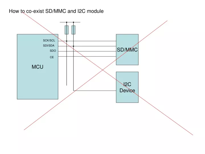
How to co-exist SD/MMC and I2C module. MCU. SD/MMC. SCK/SCL. SDI/SDA. SDO. CE. I2C Device. Typ 65mA. GPS Module. PIC 18F2550. SD. Soft UART. SPI. LCD. Soft I2C. Boost DC/DC. 2X AA Cell. VCC(3.3V). Tips to handle SD card. Initialize at PWON. Entering SPI mode.

E N D
How to co-exist SD/MMC and I2C module MCU SD/MMC SCK/SCL SDI/SDA SDO CE I2C Device
Typ 65mA GPS Module PIC 18F2550 SD Soft UART SPI LCD Soft I2C Boost DC/DC 2X AA Cell VCC(3.3V)
Tips to handle SD card Initialize at PWON Entering SPI mode Cs=clk=di high /CShigh Send dummy 80 clocks (Send 0xff x 10) /CSLow Send 0x40,0x00,0x00,0x00,0x00,0x95 Ret=GetResponse(); While(ret==0x0){ cshigh send 0xff cslow send 0x40,0x00,0x00,0x00,0x00,0x00,0x95 ret=GetResponse(); } /cshigh Send 0xff Status = Raw I/O B6 B7 DO B7 B6 DI CLK GetResponse Ret0xff Do retry{ send 0xff if(!(res&0xfe) break; } Return ret;
Tips to handle SD card address’d read /write DI A3 A2 A1 A0 0x40|17 Command 17
Least command list 6Bytes command CRC Required at CMD0 before changing SPI mode. Ignored at SPI mode. Response R1 (1Byte)
Single block read sequence /CS TX CMD16 A3 A2 A1 A0 FF RX ~ R1 D0 D1 D511 CRC1 CRC2 Single block write sequence /CS TX ~ CMD24 A3 A2 A1 A0 FF D0 D1 D511 R1 CRC1 CRC2
Single block read sequence Regular task 1s Timer invocation. Read SW. Read and Parse GPS Msg. Read Batt. Volt. Write data to SD. Exec command Update LCD. FAT16 Filesystem Software I2C Driver Software UART Driver
Software I2C Interrupt Timer Value Consider benefits between Direct execution and ISR interruption. MAX clk freq : 400kHz … 2.5us Exec step @ 8MHz … 0.5us @40MHz ... 0.1us Interrupt latency … several clks NOP SCL SDA NOP blank b7 b6 ACK SM START state ST PAYLOAD ACK data clk
Timer assignment TMR0 Software serial TMR1 Software I2C TMR2 TMR3
Software serial (receive only) top level interface Underlying i/o func in ISR if RXING { process RX until done; } else if HAS_TX process TX until done; } else { wait for RX; } char ser_getchar(void) RX buff State diagram INIT waiting for start bit TMR0L 0xff //TMR0 full count T0IF0 // Clear TMR0 flag T0IE1 // Set TMR0 INT TXSTBY RXWAITING ser_getchar() TXBUSY RXBUSY Tx not implimented RXREADY RXERR b 1.5b LSB FIRST ST 1 2 3 4 5 6 SP 0 7 RXWAITING RXBUSY RXREADY
Software serial timing consideration interrupt read bit prepare for next Counter value for Start BIT: 1.5bit = 1.563E-4s ... 195.38 256 – 195 = 61 Other BIT: 1bit = 1.042E-4s ... 124.8 256 – 125 = 131 1/9600 = 1.042E-4s ST 1.5bit 1/8 1/2 1us 8bit Timer (1/256) 2MHz 1MHz 1/4 104.17us 8MHz Prescaler 10MHz 40MHz 1.25MHz 0.8us 1/104 1/130
MBR 0 boot struct { Byte bootDescriptor; /* 0x80: bootable device, 0x00: non-bootable */ Byte firstPartitionSector[3]; /* 1st sector number */ Byte fileSystemDescriptor; /* 1:FAT12, 4:FAT16(less than 32MB), 5:拡張 DOS パーティション, 6:FAT16(more 32MB), 0xb:FAT32(more 2GB), 0xc:FAT32 Int32h 拡張, 0xe:FAT16 Int32h 拡張, 0xf:拡張 DOS パーティションの Int32h 拡張 */ Byte lastPartitionSector[3]; Byte firstSectorNumbers[4]; /* first sector number (link to BPB sector) */ Byte numberOfSectors[4]; } partitionTable; 446 P.tbl1 P.tbl2 P.tbl3 P.tbl4 firstSectorNumbers(454~457) holds offset to logical sector 0 in little endian signature ex 3E 00 00 00 3E * 512 = 7C00 PBR 7C00 JMP INST(3) struct { Byte bytesPerSector[2]; /* bytes/sector */ Byte sectorsPerCluster; /* sectors/cluster */ Byte reservedSectors[2]; /* reserved sector, beginning with sector 0 */ Byte numberOfFATs; /* file allocation table */ Byte rootEntries[2]; /* root entry (512) */ Byte totalSectors[2]; /* partion total secter */ Byte mediaDescriptor; /* 0xf8: Hard Disk */ Byte sectorsPerFAT[2]; /* sector/FAT (FAT32 always zero: see bigSectorsPerFAT) */ Byte sectorsPerTrack[2]; /* sector/track (not use) */ Byte heads[2]; /* heads number (not use) */ Byte hiddenSectors[4]; /* hidden sector number */ Byte bigTotalSectors[4]; /* total sector number */ } FAT16BPB; OEM NAME (8) BIOS Param Blk(25) Ext BIOS Param Blk(26) Boot (448) signature(2)
PBR + ReservedSectors x 512 ex 7C00h + 6x512 = 8800h 8800 FAT1 SectorsPerFat ex F5h x 512=1EA00h 8800h+1EA00h = 27200h 27200 FAT2 ex 27200h+1EA00h = 45C00h sizeof(Direntey) x rootEntries ex 32 x 512 = 16384 45C00h + 16384(dec) = 45C00 Root directory entry typedef struct DirEntry_t { Byte name[8]; /* file name */ Byte extension[3]; /* file name extension */ Byte attribute; /* file attribute bit 4 directory flag bit 3 volume flag bit 2 hidden flag bit 1 system flag bit 0 read only flag */ Byte reserved; /* use NT or same OS */ Byte createTimeMs; /* VFAT で使用するファイル作成時刻の10ミリ秒 (0 ~ 199) */ Byte createTime[2]; /* VFAT で使用するファイル作成時間 */ Byte createDate[2]; /* VFAT で使用するファイル作成日付 */ Byte accessDate[2]; /* VFAT で使用するファイル・アクセス日付 */ Byte clusterHighWord[2]; /* FAT32 で使用するクラスタ番号の上位 16 bits */ Byte updateTime[2]; Byte updateDate[2]; Byte cluster[2]; /* start cluster number */ Byte fileSize[4]; /* file size in bytes (directory is always zero) */ } ; 49C00 User Data Area
Filesystem initialization • Retrieve firstSectorNumbers • Determine head of PBR1 firstSectorNumbers x 512 • Note We does not handle other than No.1 Partition. Read MBR • Retrieve ReservedSectors, SectorsPerFAT, SectorsPerCluster, rootEntries, bigTotalSectors • Determine head address of FAT1 PBR1 + ReservedSectors x 512 • FAT2 FAT1 + SectorsPerFAT x 512 • RDE FAT2 + SectorsPerFAT x 512 • UDA RDE + 32 x rootEntries • NumSectorsOfUDA bigTotalSectors – ReservedSectors – (UDA – FAT1)/512 • UDAClusters NumSecdtorsOfUDA / SectorsPerCluster • Holds following information Read PBR1 FAT1 FAT2 SectorsPerFAT RDE rootEntries UDA UDAClusters SectorsPerCluster
Create and write a file on filesystem FAT1 FAT2 RDE UDA Create() R Look for unused RDE R Look for unused cluster W Mark 0xFF to found cluster W W Update corresponding RDE Write() W Write Data to allocated cluster W Update length of RDE W Update linked list of FAT (if data occupies beyond current cluster) W close() Flush unwritten data Update length of RDE Mark 0xFF to last used cluster
Interface layer ser_init() gps_init() GPS status register i2c_init() ser_getchr() gps_parse() ser_isr() buff buff coord LCD Display i2c_write() time info fopen() mm_init() fclose() V.Batt adc_read() V.BATT mm_read_block() spi_init() SD Card fwrite() mm_write_block() spi_trx() SW fprintf() FAT MM SPI
write(data, length) buff_len buffer[512] cluster sector • current_cluster • index of sector in the curr. cluster • address • uda + (curr.cluster -2) * • sector_per_cluster * 512 • + index_of_sector * 512 • buff_len uda
GPS Data format of GGA NNorth SSouth Time in UTC where: hhhour mmmin ss.ssssec Altitude where: dd deg mm.mmmm min(resolution 1E-4) Longitude where: ddd deg mm.mmmm min(resolution 1E-4) WWest EEast $GPGGA,hhmmss.sss,ddmm.mmmm,N,dddmm.mmmm,E, v,ss,dd.d,hhhhh.h,M,gggg.g,M,XXX.X,0000*hh<CR><LF> 2 0 13 23 25 36 38 40 48 56 Latitude Latitude unit in meter Num of STAs used range: 00 - 12 State of measuring where: 0Not working 1Working