Download
1 / 21
320 likes | 567 Views
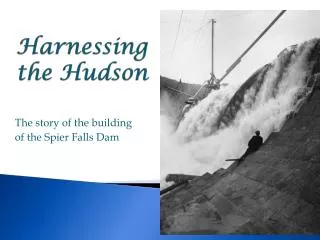
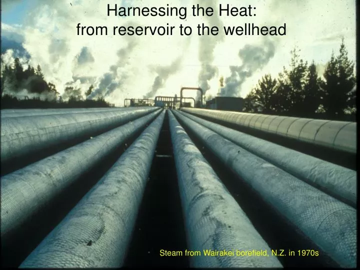
Harnessing the Heat: from reservoir to the wellhead. Steam from Wairakei borefield, N.Z. in 1970s. Heat output ~ 100 MW th. Stylized cross-section of “typical” high-temperature geothermal system (Henley and Ellis, 1983)

E N D
Harnessing the Heat:from reservoir to the wellhead Steam from Wairakei borefield, N.Z. in 1970s
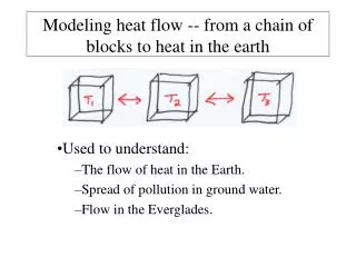
Heat output ~ 100 MWth • Stylized cross-section of “typical” high-temperature geothermal system (Henley and Ellis, 1983) • upflowing plume of hot water at 250º – 350ºC from 3 – 5 km depth; deep heat source usually cooling intrusion • isotopes of water show upper plume is predominantly meteoric water Geothermal “reservoir” (1 – 3 km depth) • more extensive “outflow” zone in upper 1 – 2 km of plume where there is mixing with surrounding cooler waters, boiling in the hotter parts of the plume, and merging with the surface ground water as springs and underflow • for system beneath a volcano, steam outflow (fumaroles, maybe be closer to deep upflow zone than the hot springs, which may be down-slope
The simplest form of harnessing the heat • If the geothermal fluid stays liquid, then the reservoir heat extraction is relatively simple • cooling of production water yields the heat (mass flow * specific heat* temperature drop) (specific heat water = 4 kJ/kg/ºC) • issues are efficiency of heat exchanger, and possible scaling potential of the cooled water, and size of the hot reservoir (subjects of later lectures)
A good water well (artesian) can have water flowing at ? 1 m/s at the wellhead (2 mph) A good geothermal well flows at?? 343 m/s or 768 mph This is the speed of sound in air
Video clip of opening a geothermal well with vertical discharge; watch for: 1. Initial high frequency noise (first few seconds) is from bleed line to prevent too much well-head pressure while closed 2. The first few turns of the master valve take two guys because of that pressure; these valves are usually opened as quickly as possible to avoid damage from something coming up the wellbore (e.g. rock fragments) 3. There is a change from high frequency noise in discharge to lower frequency when discharge changes from dry steam, to steam and water (2-phase). Can also then see wet condensate drifting from plume 4. Surging discharge from the well as it unloads the initial static column of liquid; this process can take 15 – 30 minutes; (this video clip is edited – its about a minute long) 5. This is a 100 MWth well = ~ 10 MWe (this well has a feedzone at about 250ºC; TH2 in Tauhara field, N.Z. Video courtesy of Contact Energy Ltd.)
Water: liquid/vapor relationships • We all know as atmospheric pressure decreases with elevation the boiling point of water also decreases…. • what is the boiling point in Salt Lake City (elevation ~ 4500 ft asl)? Note: 1 bar absolute = 0 bar gauge pressure
previous slide looked at curve for < 100 ºC • coexisting water and steam lie on the saturation (boiling point) curve • Boiling process shown here as pressure drops with ascending water (could be hot water rising up a well, or in a fracture zone) • Reverse process would be condensation (starting with vapor and increasing pressure or decreasing temperature) Liquid and steam Pressure (depth) of first boiling Ascending water at 250 ºC Critical point
Steam and water have very different properties! Steam tables are very useful for quick calculations of steam-water properties Enthalpy is “usable heat” (spec. heat * temp.); density = 1/specific volume Note at 200 ºC (~15 bar), water has 30% the heat content, but 100 times the density of steam
Pressure-depth relationships(let’s convert pressure axis to depth axis) • Pressure = density * grav. accel.* thickness In metric units, pressure is in Pa, but its very small! In cold water, 1 bar (100 kPa) = 1000 kg/m3 * 10 m/s2 * 10 m In rock with density of 2500 kg/m3 100 bar = 2500 kg/m3 * 10 m/s2 * 400 m (= 10MPa) Q1: what would be the pressure of cold water at 400 m depth? Q2: what would be the pressure of hot water (800 kg/m3) at 400 m depth?
In geothermal systems we are interested in the density of the continuous pore fluid phase • Usually this is hot hydrostatic, but steam zones may be important (analogous to vadose zones in ground water systems)
Boiling Point for Depth Relationship (BPD) (In fluids, total vapor pressure is the sum of the partial pressures of each vapor component; e.g. Ptot = PCO2 + PH2O)
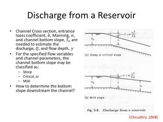
Draw down = 5 bar (50 m) What happens when we draw down a cold water well? What about a geothermal well?
What would the discharging profile look like for a geothermal well?
The temperature profile confirms the depth of initial boiling
Calculating steam/water mixtures Steam with enthalpy Hse Initial water Ti, Pi, Hli pressure drop (and temperature drop) end state: Te, Pe Liquid with enthalpy Hli • We do simple conservation of heat calculation (initial vs. end): • heat = enthalpy (kJ/kg) * mass flow (kg/s) = kJ/s = kW • assume initial mass flow = 1; end steam fraction = m • Hli * 1 = m * Hse + (1-m) * Hle • m = (Hli – Hle) / (Hse – Hle) note: (Hse – Hle) = latent heat of steam (end) • and 1-m (water fraction) = (Hse – Hli) / (Hse – Hle)
Example of calculating steam fraction:assume upflowing water at 240 ºC; end is atmosphere @100 ºC • Enthalpy initial water = 1038 kJ/kg (from steam tables) • Enthalpy of end water = 419 kJ/kg ( “ ) • Difference = 619 kJ/kg • Latent heat steam at end = 2257 kJ/kg • Steam fraction = 619/2257 = 27% • Water fraction = 73% • Steam fraction would be smaller if end state is the separator pressure set for inlet of turbine • At 100 ºC, specific volume of steam is over 1000 times that of 240 C water. Volume flux up wellbore amount to about 300 times increase!
We now understand how steam and water get to the wellhead – let’s generate electricity!