Download
1 / 21
210 likes | 321 Views
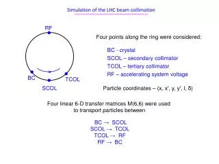
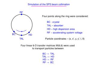
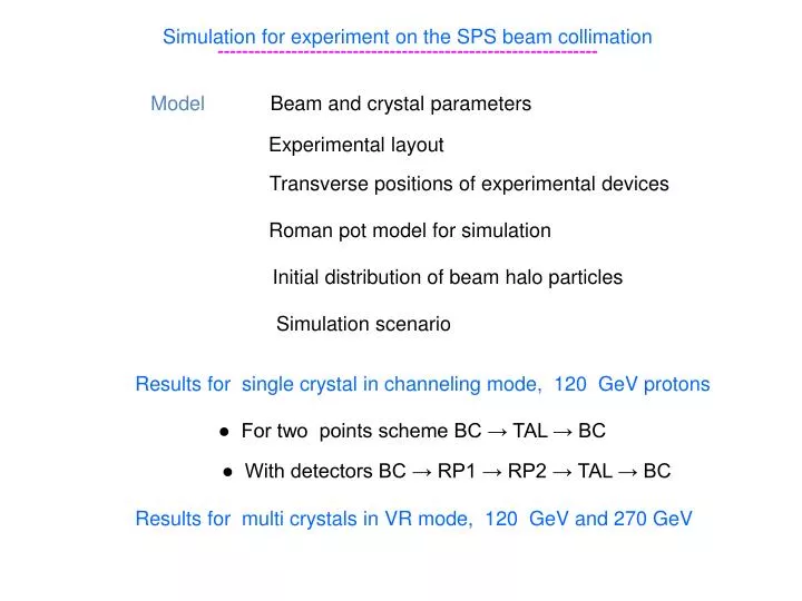
Simulation for experiment on the SPS beam collimation --------------------------------------------------------------. Model. Beam and crystal parameters. Experimental layout. Transverse positions of experimental devices. Roman pot model for simulation.

E N D
Simulation for experiment on the SPS beam collimation -------------------------------------------------------------- Model Beam and crystal parameters Experimental layout Transverse positions of experimental devices Roman pot model for simulation Initial distribution of beam halo particles Simulation scenario Results for single crystal in channeling mode, 120 GeV protons ● For two points scheme BC → TAL → BC ● With detectors BC → RP1 → RP2 → TAL → BC Results for multi crystals in VR mode, 120 GeV and 270 GeV
Beam and crystal parameters -------------------------------------- Energy of protons – 120 GeV and 270 GeV Normalized emittance at 1 σ – 1.5 mm∙mrad Tune Qx=26.62 , Qy=26.58 Beam – unbunched ----------------------------------------------- (111) Silicon crystal Bend angle α=150 μrad → impact parameters with TAL 6÷8 mm → achievable for LHC energy Crystal length L=1 mm, thickness T=0.5 mm Compromise between optimal parameters for SPS and required for LHC
BC and RP2 → close to locations with β=βmax RP1 → small β but phase advance is close to optimal
Transverse positions of experimental devices ------------------------------------------------------ BC – distance from closed orbit → Xbc=6σbeam particles should first hit crystal RP1, RP2 , TAL → at 6σbeam +Xof shifted by Xof from crystal position Xof → amplitude increase due to MS in BC with angle 4.25 θms This practically excludes hits of TAL after BC passage in amorphous mode Probability to be channeled at following passages increases TAL → additionally shifted by the value of non-registered area of RPs 6σbeam + Xof + Tnr, where Tnr=800 μm
Roman pot model for simulation --------------------------------------- Detector dead area – 500 μm Sensitive area distance from RP bottom – 800 μm
Roman pot model for simulation --------------------------------------- Three transverse areas with different contentwere considered for RPs 1. XRP < X < XRP+150 μm → bottom of RP, Lb=3 cm (Al) 2. XRP+150 μm < X < XRP+300 μm → slot of RP, Ls=400 μm (Fe) 3. X > XRP+300 μm → detector area of RP, Ld(RP1) = 400 μm (Fe) + 900 μm (Si), Ld(RP2) = 400 μm (Fe) + 1500 μm (Si) ----------------------------------------------- Processes considered for particles crossing RPs ● multiple Coulomb scattering ● ionization losses ● inelastic nuclear interactions
Initial distribution of halo particles --------------------------------------- Normalized betatron amplitude at BC → xm=xbc+∆xm Amplitude increase Δxm is a random value P(∆xm)=exp(-∆xm/λ), λ=0.1 μm, ∆xm=–λ∙ln(ξ1) Interval betatron phases of particles hit BC ∆φ=arccos(1/(1+∆xm/xbc)) Random phase from this interval Φ(ξ2)=2∙∆φ(ξ2-0.5) Horizontal coordinates x(ξ1,ξ2)=xm(ξ1)∙cos(φ(ξ2)) x΄(ξ1,ξ2)=-xm(ξ1)/βx (sin(φ(ξ2)+α∙cos(φ(ξ2))) Distributions of vertical coordinates (y, y΄) and momentum deviation δ=∆p/po P(y)=P(y΄)=P(δ)=δ(0)
Simulation scenario ------------------------- For particle tracking → (1) liner approach was used for SPS (2) the only aperture restrictions are in the crystal collimation area We transport particles along SPS through forth azimuths BC → RP1 → RP2 → TAL using four transfer matrices M(6,6) Start point → BC azimuth Final points → (1) absorption in TAL (2) Inelastic interaction in either BC or RP1, RP2,TAL Collimation efficiency losses only due to inelastic nuclear interactions
Collimation without detectors ------------------------- Impact parameters Number of passages Perfect alignment and near θo=0 θo=20 θo=40 θo=-20
Collimation without detectors ------------------------- Far from perfect alignment Impact parameters Number of passages θo=75 Amorphous diffusion θo=-75 VR drift
Collimation without detectors – orientation dependencies --------------------------------------------------------------- Efficiency Average impact parameter Edge fractions Efficiency at θo=0 → larger 99.9% For angles ±θc → larger 99% Edge fractions near θo=0 → smaller 2 and 3%
Collimation with detectors ------------------------- Efficiency Edge fractions Collimation efficiency Pc for θ≠0 decreases → losses in dead area of detectors Probability of coordinate registration in RP2 → Pr2 < Pc Probability of angle registration Pr12 for θ≠0 decreases fast → amplitude increase rate to pass dead area of RP1 is lower
Monitor of beam losses near BC ----------------------------------- Monitor indications ~ particle losses due to inelastic interactions in BC Beam losses in BC Beam fraction lost in BC is the compliment to the other one absorbed in the collimator Ploss=1-Pc 3 2 1 Minimum (1) – due to channeling in BC Losses in VR area (3) are smaller than in random → angular deflections are larger → number of BC passages to be absorbed in TAL reduces Minimum (2) near θo=-α → VR always increases the betatron amplitudes → the whole VR area is in one side of beam envelope inclination
Multi reflections by sequence of bent crystals – SVR ----------------------------------------------------------- Optimal bend radius for VR → Ropt=10 Rc, for 120 GeV and (111) Si Rc=0.21 m VR deflection angle for R=2 m → θvr=21 μrad Seven subsequent reflections can give a deflection of about 150 μrad Angular acceptance for parallel SVR → θac=α-(Nθvr+θc), θc≈20μrad Our parallel SVR parallel optimized N=7, (111) Si, L=0.5 mm, R=2m → 250 μrad θsvr=148.2 μrad σsvr=27.8 μrad
Collimation by parallel SVR for 120 GeV ----------------------------------------------- Impact parameters Number of passages Middle of MVR area θo=-210 Edge of MVR area θo=-290 Channeling in one of crystals θo=0 VR in subsequent crystals reduces deflection
Collimation by parallel SVR – orientation dependencies -------------------------------------------------------------- Efficiency Average impact parameter Edge fractions MVR Efficiency for VR and CH areas – 99% Average impact parameter for MVR area → larger than 5 mm Edge fractions for MVR area → 5% and 9 %
Collimation by parallel SVR – with detectors ----------------------------------------------------- Registration efficiencies Beam losses increase twice – 2% Collimation efficiency – 98% Probability of coordinate registration in RP2 is close to 100% → Pr2 ≈ Pc Probability of angle registration Pr12 > 70% for MVR and CH areas
Collimation by unparallel SVR for 120 GeV protons ------------------------------------------------------------- Every next crystal is tilted by δθ≈-θvr → δθ=-20 μrad Acceptance for MVR is limited only by the beam broadening θac=α-θc-2σmvr, where σmvr – RMS deviation of the multi reflected beam θo=0 Particles deflected due to channeling avoid to be reversely deflected by VR in subsequent BC They generate max near x=15 mm at TAL θo=50 So, positive orientations of SVR are also appropriate for collimation θo=120
Collimation by unparallel SVR for 120 GeV protons ------------------------------------------------------------- Average impact parameter Edge fractions CH MVR CH MVR MVR area increases twice up to 200 μrad Edge fractions in MVR area are smaller → 2% and 3.5% Angular acceptance for channeling increases N times
Collimation by unparallel SVR for 270 GeV protons ------------------------------------------------------------- Optimal bend radius for VR → Ropt=4.6 m for 270 GeV in (110) Si, Rc=0.46 m VR deflection angle for R=4.6 m → θvr=16 μrad Ten subsequent reflections can give a deflection of about 160 μrad Unparallel SVR, δθ=-16 μrad → N=10, (110) Si, L=1 mm, R=4.6 m, α=217 μrad θmvr=157.8 μrad σmvr=20.9 μrad
Collimation by unparallel SVR for 270 GeV protons ------------------------------------------------------------- Efficiency Average impact parameter Edge fractions CH MVR MVR CH Optimized unparallel SVR ←→ parallel SVR Larger acceptance for MVR and increased N times acceptance for CH SVR works in CH mode as well as in MVR mode Collimation in the angular area of 2α width