Download
1 / 12
160 likes | 535 Views
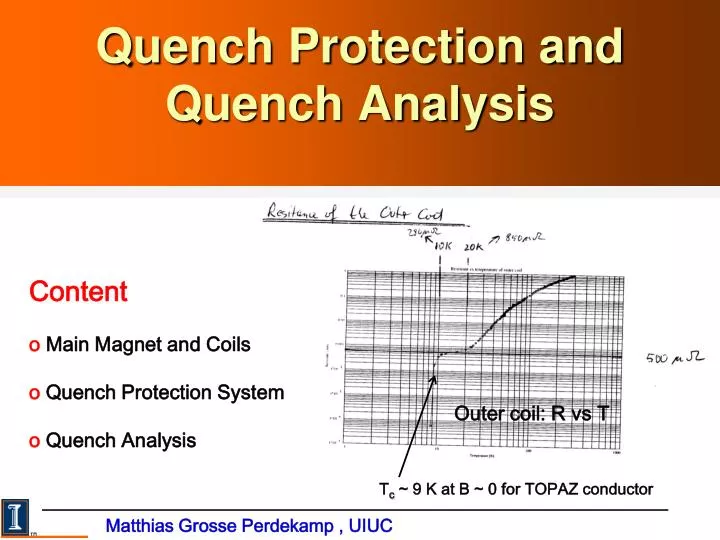
Quench Protection and Quench Analysis. Content o Main Magnet and Coils o Quench Protection System o Quench Analysis. Outer coil: R vs T. T c ~ 9 K at B ~ 0 for TOPAZ conductor. Matthias Grosse Perdekamp , UIUC. Magnet and Coils. Outer & inner coils: 48 turns

E N D
Quench Protection and Quench Analysis Content o Main Magnet and Coils o Quench Protection System o Quench Analysis Outer coil: R vs T Tc ~ 9 K at B ~ 0 for TOPAZ conductor Matthias Grosse Perdekamp , UIUC
Magnet and Coils Outer & inner coils: 48 turns Coil cold mass: 6.2 tons Stored energy : 6.1 MJoule B=1.451 T I=5200 A g-2 Collaboration Meeting at FNAL
Outer Coils Conductor: NbTi/Cu(TOPAZ) TC = 6K for B on TC = 9K for B 0 IC > 8 kA but Ion ~ 5.2 kA 2 Outer Coils: Upper & Lower Outer Coils 24 windings each both mounted to conti- nuous Al-mandrel with Rm=11.6 uOhm indirect cooling with lqHe pipes attached to mandrel. Top ~ 5 K g-2 Collaboration Meeting at FNAL
Inner Coils Conductor: NbTi/Cu(TOPAZ) TC = 6K for B on TC = 9K for B 0 IC > 8 kA but Ion ~ 5.2 kA 2 Inner Coils: Upper & Lower Inner Coils 24 windings each separate cryostats + Al-mandrels indirect cooling with lqHe pipes attached to mandrel. Top ~ 5 K g-2 Collaboration Meeting at FNAL
Detection of Resistive ΔVs in Coil Redundant voltage probes at the top and bottom of each coil -- few bad contacts after thermo cycles. Must be checked ! Required sensitivities: Outer coil ΔV>100 mV Interconnects ΔV> 5 mV Use differences, eg. VOU-OT, tocancel inductive voltages (eg. ramp ) + noise. g-2 Collaboration Meeting at FNAL
Readout of Voltage + Temperature Information Voltage: Front-End: noise filtering “quench protection circuit” QPC output to (I) Allen Bradley PLC (ladder logic) quench trigger decision in PLC (realtime processor) (II) Fast CAMAC WFD for readout voltages read every 4 ms for 16s then every 32ms for 260s “ring buffer” to document history prior to quench trigger. Termperature: 8 temperature probes for outer coil and inner coils, read every 2 seconds. g-2 Collaboration Meeting at FNAL
Example: VOU-VOL before quench ~ 70 sec. prior to quench A small piece of the conductor of the outer lower coil “goes normal” but cools down again. Length of normal conducting conductor section exceeds mimum propagation length Quench ! Time [s] g-2 Collaboration Meeting at FNAL
Example: Temperatures, energy extraction at I=1500A and I=2450 A I=1500 A Tmax~ 10k, back to Lq He < 600 s I=2450 A Tmax~ 20k, back to Lq He ~ 1100 s g-2 Collaboration Meeting at FNAL
Quench Analysis Mandrel vs Coil transformer ! Solution known analytically, fit to data to fix L, M and R. L inductances of coil and mandrel, M, mutual aceptance g-2 Collaboration Meeting at FNAL
Quench Analysis:I = 0.1kA to 5.2 kA At I = 5.2 kA Estored= 6.1 MJoule Edump-resistor = 0.39 Estored Emandrel= 0.25 Estored Ecoil= 0.36 Estored g-2 Collaboration Meeting at FNAL
“Quench Back” • Tmax= 37 K • Quench back: • The transformer coupling of • the outer mandrel to the • magnet coil induces resistive • heating in the outer mandrel • uniform low temperature, • quench and eddy current • pattern g-2 Collaboration Meeting at FNAL
Summary o Quench back leads to uniform and modest temperature increase around the outer coil, Tmax = 37 k. coil integrity guaranteed small and uniform umbrella effect ( good reproducibility of fields) o Important to check integrity of voltage tags (this potentially could require access to the interior of the cryostats. o Make sure to acquire front end electronics and readout from BNL. o Suggest to upgrade electronics and readout to state of the art (mainly to make sure that there will be expertise on the quench protection and recording systems in the collaboration). g-2 Collaboration Meeting at FNAL